 12-31-2012, 03:23 AM
|
#1
|
|
Seeking 9s on M6...
Drives: 2012 2SS/RS LS3 aka "BlackWidow"
Join Date: May 2012
Location: Houston, TX
Posts: 397
|
Alky Control Meth Kit w/trunk tank Install
I finally got around to installing my new Alky control Meth kit while I had some time off over the holidays. The install guide was very helpful, but left me with lots of questions given Im new at this stuff (I had a hard time validating the parts list J). Julio was also taking time off over the holidays, but to my surprise, he quickly responded to all my questions in e-mail! So I was able to complete my install in a few days (taking breaks for family activities). Thank you Julio!
I thought I would include some of what I learned and include some pictures I snapped along the way in case any other newbies are attempting this install. This is not a complete DIY, but may help aid the instructions that are included with the kit. Sorry in advance, I used my iphone for pics and was in my dark garage because it was cold outside...
One thing I liked about this install is I was able to do it in small chunks and the car remained drivable throughout.
I had to go with the trunk mount tank because I have a CAI cold air intake and scoop which already removed my windshield washer bottle which is typically used as the meth tank.
So I started with the tank installation:
Trunk Tank Prep: (you need to supply a bracket and HW to secure the tank)
The tank fits nicely on the driver side of the trunk towards the back (pic 1). You need to pull off the trim around the trunk to fit it into place (start w/the plastic wall on the back, and then the driver side wall leave the front attached for now and push it up out of the way; I completely removed it later to modify it).
I bought a piece of 1x1/8 aluminum to bend a bracket to hold the tank in place (Pic 2). I also bought a few 1.5" ¼ bolts to hold it in place. I marked the 2 holes to drill (make sure they are outside of the main support so you can access them from under the car (pic 3)). I put washers on both sides of the bolt and had a helper to secure the bolts in place. (I used a nylon lock nut to secure the tank to the bolts after the side panel was modified to fit the tank later).
Pic 1: Tank in trunk on drivers side:
 Pic 2: Tank bracket w/o tank
on bolts.
Pic 2: Tank bracket w/o tank
on bolts.
 Pic 3: Tank bolt from under car
be sure to drill outside of support beam (look underneath before you drill).
Pic 3: Tank bolt from under car
be sure to drill outside of support beam (look underneath before you drill).
 Mount Pump:
My pump came mounted to a bracket w/4 rubber spacers and 4 self tapping machine screws. I used 3 of the screws to secure the pump to the spare tire well. Making sure the Styrofoam pump holder still fit in place. The one bottom screw was a pain, so I didnt bother w/the 4th
it feels solid. (pic 4 shows my initial holes, and pic 5 shows the pump installed and hooked up).
Pic 4: location to mount the pump.
Mount Pump:
My pump came mounted to a bracket w/4 rubber spacers and 4 self tapping machine screws. I used 3 of the screws to secure the pump to the spare tire well. Making sure the Styrofoam pump holder still fit in place. The one bottom screw was a pain, so I didnt bother w/the 4th
it feels solid. (pic 4 shows my initial holes, and pic 5 shows the pump installed and hooked up).
Pic 4: location to mount the pump.
 Pic 5: Install Pump This picture is with hoses and cables hooked up. In hind sight, I would have made the intake hose point to the top of the pump (vs. the bottom as seen here). Then the hose to the tank can be shortened and would be a direct line. The output connector should still point to the bottom of the pump. The one nice thing about the longer intake hose, was it allowed me to move the tank around during the install w/o disconnecting the hose.
 Running the hose and wires through the cars interior (and modifying the trunks trim for the tank):
Now we need to remove the back seat and the driver side wall panels (all easier than I thought). I found steps to remove the seat on this forum from terry_b:
Running the hose and wires through the cars interior (and modifying the trunks trim for the tank):
Now we need to remove the back seat and the driver side wall panels (all easier than I thought). I found steps to remove the seat on this forum from terry_b:Removing Rear Seat
a) There are 2 clips at the front of the seat, about center of the "bucket" portion, one on each side. Firmly lift the seat straight up. Push the seat belt latches through to the bottom of the seat.
b) The bottom portion will fold upward basically flush with the upper portion. It will spring back down so you have to hold it up there.
c) There is a large nut in the center you need to remove, 18mm deep socket.
d) At each corner there are 2 bolts to remove, the one on the bottom is easy to spot but there is one above it partially hidden. 15mm socket
e) Pull the loop to unlatch the upper portion and lift out. Be VERY mindful of the metal at the bottom of the seat to prevent harming your interior trim.
With the seat removed, you can remove the side panels by firmly pulling away from the wall. After the back seat side panel is removed, you can completely remove the trunk driver side wall to modify it (pic 8). Now you can route the hose, pump wires and tank low level wires towards the front of the car. Note the panel next to the drive seat pulls straight up, and the panel by the drive floor mat pulls back toward the back seat. There is plenty of room to route the hose and wires through the side panels. (Pic 7 & 9)
Pic 6: removal of back seat
note the white clips on the front, single main bolt in the middle rear, and 2 bolts on each side rear.
 Pic 7: side wall removed allows you to take the trunk side wall completely out and you can route the hose, pump wires, & tank low level wire towards the front of the car. I attached them to the wiring bundle w/zip ties.
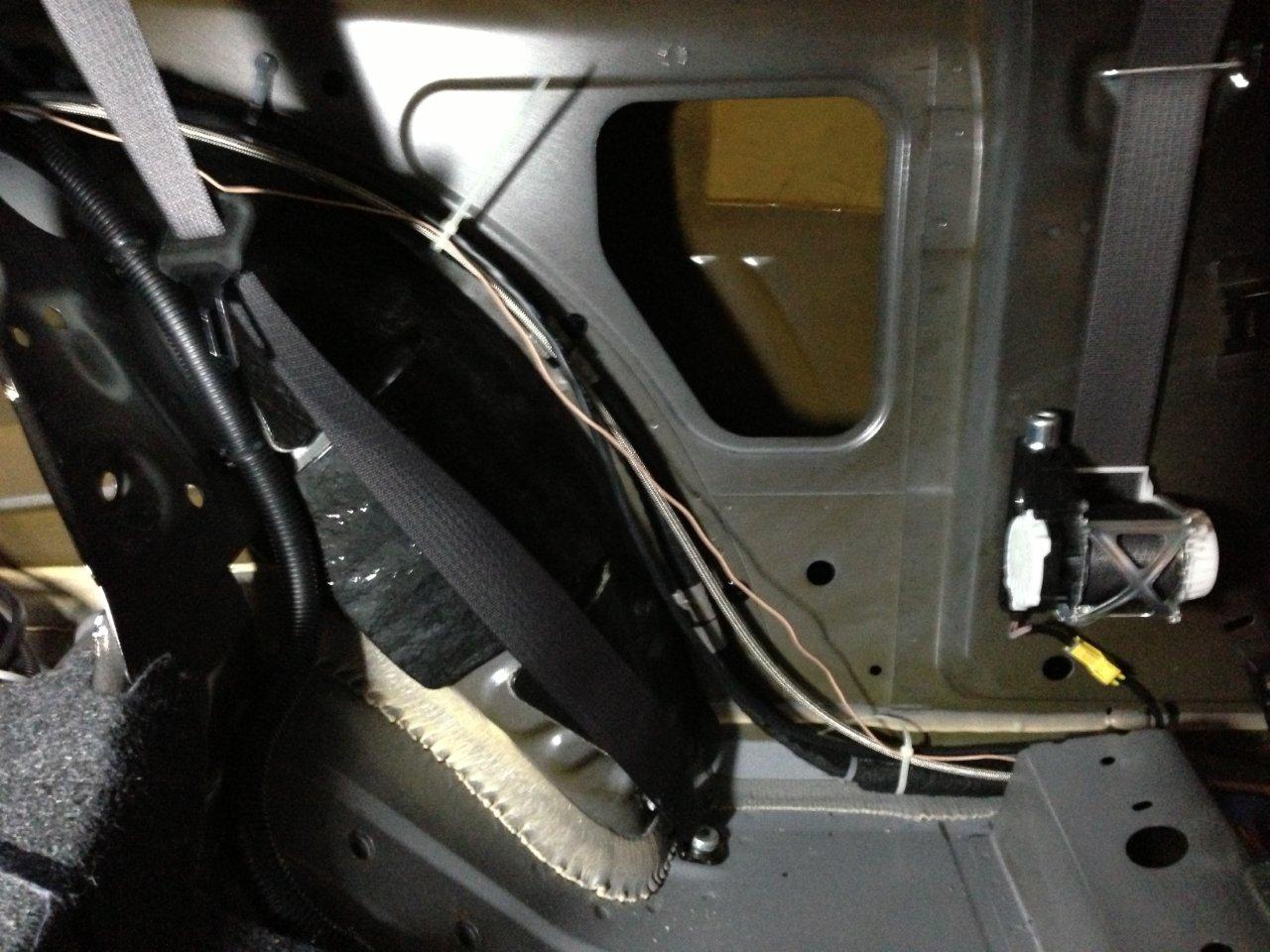 Pic 8: I used a razor knife to cut the shape of the tank into the side wall so it could slide in place. I left the insulation connected.
 Pic 9: routed hose, pump wires and low level wire along existing loom with wire ties.
 Finish the Tank Install.
Now that the trunk panel is modified, and the hose and wires are routed, you can now reinstall the trunk wall panels and then permanently secure the tank. Dont forget to add the vent hose at the top and feed it through the hole already there (just pull the plug out its in the perfect place) (Pic 10a).
I also took the time here to modify the wheel well cover so it would fit (pic 10).
Then everything fits into place (pic 11).
Last step here is to fit the vent tube
I zip tied my vent end to the rear bumper (cut the hose to length, attach the vent end piece I had no idea what that wasJ) (pic 12)
Pic 10: Cut a notch for the hose from tank to pump.
Finish the Tank Install.
Now that the trunk panel is modified, and the hose and wires are routed, you can now reinstall the trunk wall panels and then permanently secure the tank. Dont forget to add the vent hose at the top and feed it through the hole already there (just pull the plug out its in the perfect place) (Pic 10a).
I also took the time here to modify the wheel well cover so it would fit (pic 10).
Then everything fits into place (pic 11).
Last step here is to fit the vent tube
I zip tied my vent end to the rear bumper (cut the hose to length, attach the vent end piece I had no idea what that wasJ) (pic 12)
Pic 10: Cut a notch for the hose from tank to pump.
 Pic 10a: Vent tube through existing hole:
 Pic 11: At this point, the trunk sides are all back in place, reinstall the backseat wall panel and reinstall the back seat. Hose and wires are in the drivers foot area. I also modified the trunk floor carpet by simply cutting a line at the front of the tank to allow the front to lay flat while the back inadvertainly hides the tank (but then remove the trunk floor and wheel well cover as you will need to check for leaks later on
 Pic 12: vent tube zipped tied to inside of the rear bumper:
 Finish routing hose:
The wires stay under dash, hose continues through to the engine. So there is an available hole through the firewall all the way to the left of the clutch and about 6-8 inches up. Unfortunately for me, I already had that utilized to the point the hose would not fit. So I had to drill a new hole. I positioned it about 6-8 inches below the pre-existing one. Hose goes through and then eventually the red power wire and green MAP wire come back though from under the hood to under the dash.
Finish hoses & nozzles under the hood:
My hose made it about a 1.5 through the firewall, thats where you connect the inline filter (made of 4 brass pieces all w/arrows pic 13), and then connect the next longest hose which goes on to the T connector and then the nozzles (Pic 14).
I have a whipple w/a CAI air intake, so there is a thick rubber elbow where the nozzles go. The nozzles come w/2 rubber padded washers that are intended to be inside and outside the air intake tube. I was only able to use the inside washer, and I had to cut off the rubber in order to get the nozzles threaded. (Pic 15).
Pic 13: Inline filter connecting feed hose from pump to the feed hose to the T connector.
Finish routing hose:
The wires stay under dash, hose continues through to the engine. So there is an available hole through the firewall all the way to the left of the clutch and about 6-8 inches up. Unfortunately for me, I already had that utilized to the point the hose would not fit. So I had to drill a new hole. I positioned it about 6-8 inches below the pre-existing one. Hose goes through and then eventually the red power wire and green MAP wire come back though from under the hood to under the dash.
Finish hoses & nozzles under the hood:
My hose made it about a 1.5 through the firewall, thats where you connect the inline filter (made of 4 brass pieces all w/arrows pic 13), and then connect the next longest hose which goes on to the T connector and then the nozzles (Pic 14).
I have a whipple w/a CAI air intake, so there is a thick rubber elbow where the nozzles go. The nozzles come w/2 rubber padded washers that are intended to be inside and outside the air intake tube. I was only able to use the inside washer, and I had to cut off the rubber in order to get the nozzles threaded. (Pic 15).
Pic 13: Inline filter connecting feed hose from pump to the feed hose to the T connector.
 Pic 14: Hose from filter connect to T and then to nozzles. Julio recommended the feed hose to run under the air intake tube, but I was concerned about the belt rubbing it. I put a black loom around it and I think it looks good (picture does not have the loom).
 Pic 15: Nozzles on thick rubber elbow. Single washer inside w/o rubber.
 7) At this point, its all wiring It is pretty straight forward
especially when you understand its MAP OR MAF converter
Im embarrassed to say I was trying to figure out how to wire the MAF converter to my MAP signal wire until Julio set me straight (as I stated earlier Im a new at this stuff).
7) At this point, its all wiring It is pretty straight forward
especially when you understand its MAP OR MAF converter
Im embarrassed to say I was trying to figure out how to wire the MAF converter to my MAP signal wire until Julio set me straight (as I stated earlier Im a new at this stuff).
|

|

|