Quote:
Originally Posted by anthony.

very nice! where did you wire the engine bay lighting to? i would like to wire just a light in my intake box as well.
|
For the ground I used the radiator support bolt where my apex catch can is mounted.

For the positive, if you open your fuse box then look to the bottom left you will see a 10mm nut holding down a wire. This is the main power coming into your fuse box. This is where I installed my positive power lead. The multicolored wire is from one of the LED strips and is blocking the view of my power wire but it is right behind it. You can also see that I mounted the LED RF Controller module onto the left side of the fuse box.

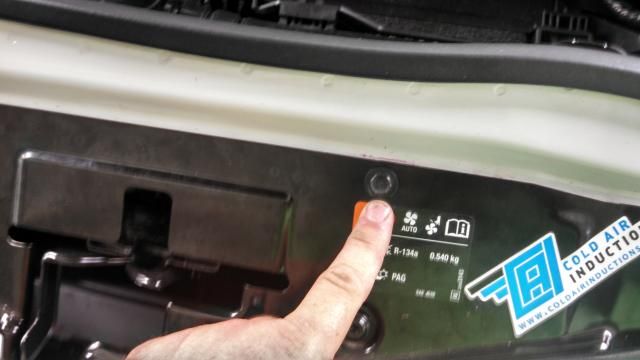
Inside the box I mounted them like the following picture.(it is looking from inside the CAI box out towards the front of the car.

I then added a small strip of 3M tape to the LED strip wire and ran it under the front lip of the engine compartment. Thanks to taking this picture I saw that I had to fix the piece of 3M there that had came off the back of the wire....

To get into the grille area you only have to remove 4 10mm bolts, And then 6 of the push type fasteners from this plate and remove it:

10mm bolt
For the other 6 fasteners. Pull up on the middle section( you can pull it all the way out or not)then the bottom section can be removed.

Once that plate is removed you can mount your grille light strip to the crash bar or as I did to the underside of the front fascia. Then to get your LED strip wire to the controller, I ran it through the hole behind the hood latch and into the engine compartment. (Picture was taken after I had put the plate back on, but you can see the wire running through the hole)Then along the front edge of the engine compartment and over to the RF controller.


The next picture is to show where The wire comes into the engine compartment from the grille area. It is the one on the far right. It is a pre cut square hole.
The light strip in the back I mounted under the lip in the back over the back of the engine cover.

Ran the wire under the lip in the back towards the passenger side of the car
(You can see the wire in the picture coming out from under the lip and to the passenger side strut tower.

then around the back of the left side strut tower and over to the RF controller.

I used a lot of zip ties also. Anywhere that a wire ran close to a wiring harness or another cable, I secured it with a couple of zip ties.
Last step is to plug all the LED strips into the RF controller. Plug the controller in and give it a test.