I have seen several post/threads about people asking how to hook this particular shift light up.
After several emails back and forth with Raptor Performance I was able to get the correct wiring and correct pin on the PCM to install this correctly.
here goes.
material
1 Raptor shift light w/accessories
Wire loom about 20ft.
Butt-splice connectors 16-14 guage
16-14 gauge T_Tap connectors.
16-14 Spade connectors
1- 16-14 gauge d-ring connector for 5/16 bolt
One 5/32 machine screw and nut, about 3/8" long
zip ties
shrink wrap
16 or 14 gauge wire white and green
Tools you will need
heat gun
Drill
1/2 drill bit,
5/32 drill bit
Electrical tape.
10 mm socket with ratchet
1. First thing to do is decide where you would like to mount your shift light.
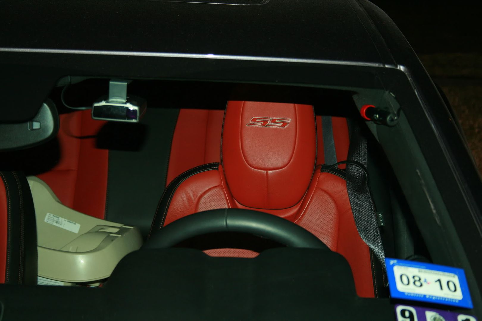
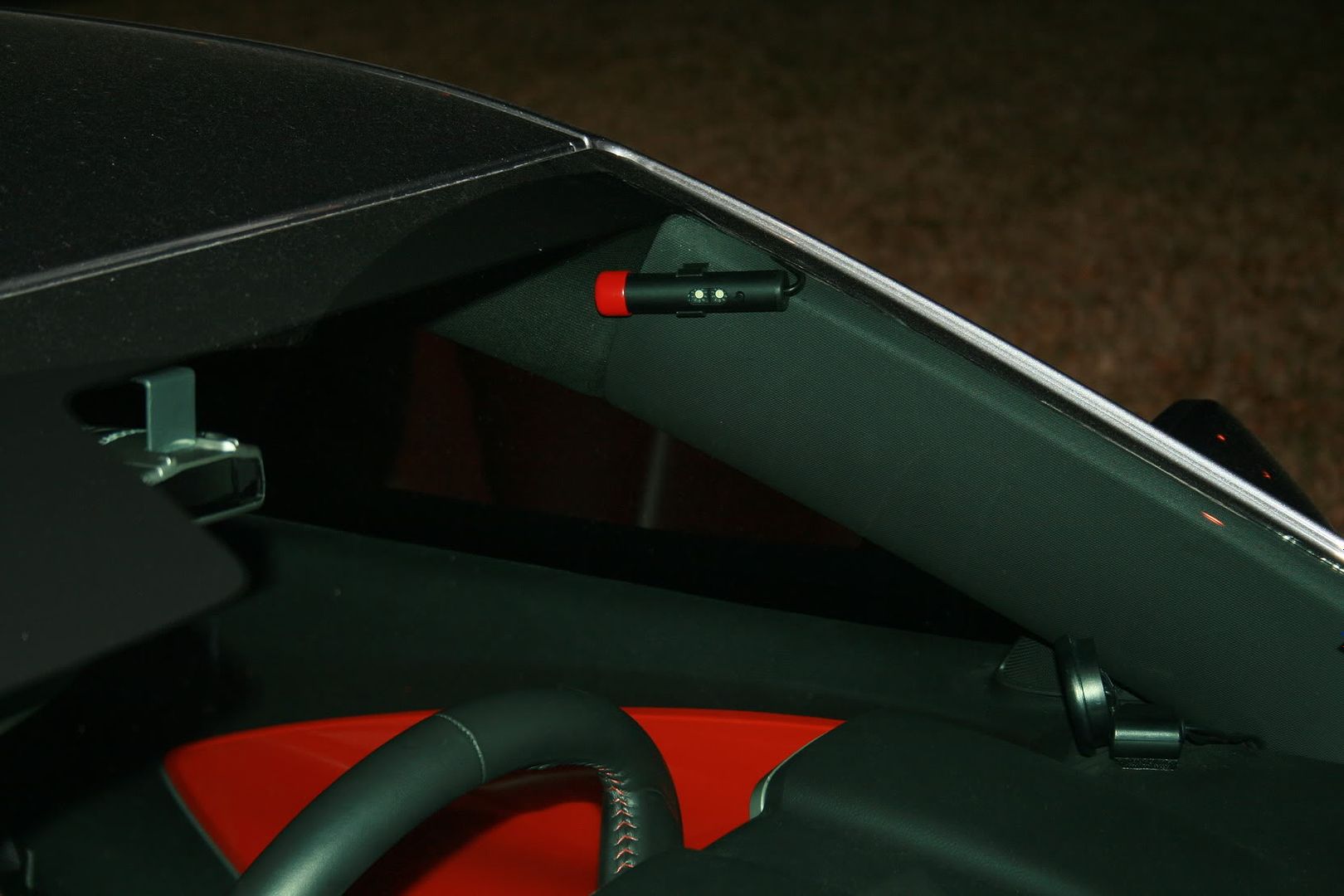
I chose the far upper corner of the driver windshield, as it is out of site, but yet still in my peripheral. I did have to drill 1 5/32 hole and obtain a machine screw, and nut to fit the corresponding hole.
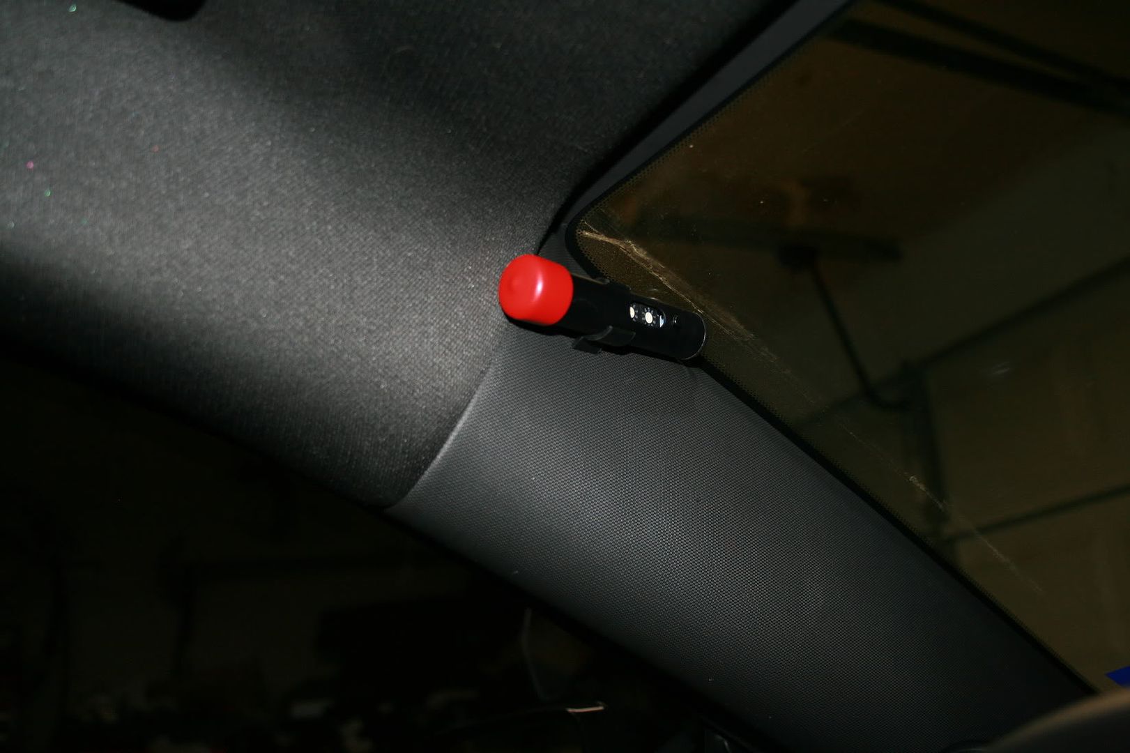
So now that the decision to mount it here has been made, Place the light with the base attached, and hold the light in it's position. Once you like it. make a mark along the base of the stand.
Next remove the A-pillar cover, and align the base up with the line you made( with out the shift light in the base). Once you have it lined up, take a Sharpie and make a mark for the hole. Now drill out the hole. Bolt the base to the A-pillar cover.
Now take the light, and mount it back in the base. Remove the Fuse panel cover on the side of the dash, and re-install the A-pillar cover, while doing this fish the wire down behind the cover, and down into the Fuse Block area on the side of the dash. Snap the A-pillar cover back into place, making sure that you don't have any excess wire hanging out. Just enough to not put a lot of tension on the connector on the back of the light.
Now comes the fun part.
Disconnect the Negative side of the Battery
Strip the black protective coating back as far as you can ( I stripped mine till about 6inches before it went up into the A-pillar. I had already had tapped into the fuse block on the secondary side of the fuse( protected side) in a previous install. So I had an available switched hot circuit available to me. If you don't you will need to locate one. whether it be from the ignition source, or some other spot.( Cut the red wire to fit, save the excess you will need it later). I would stay away from anything that has to do with Onstar, or any safety aspect of the car.(airbags etc.)
Now for the Ground there is a bolt here. (Cut the black wire to mount here. (save the excess wire you will need it later).
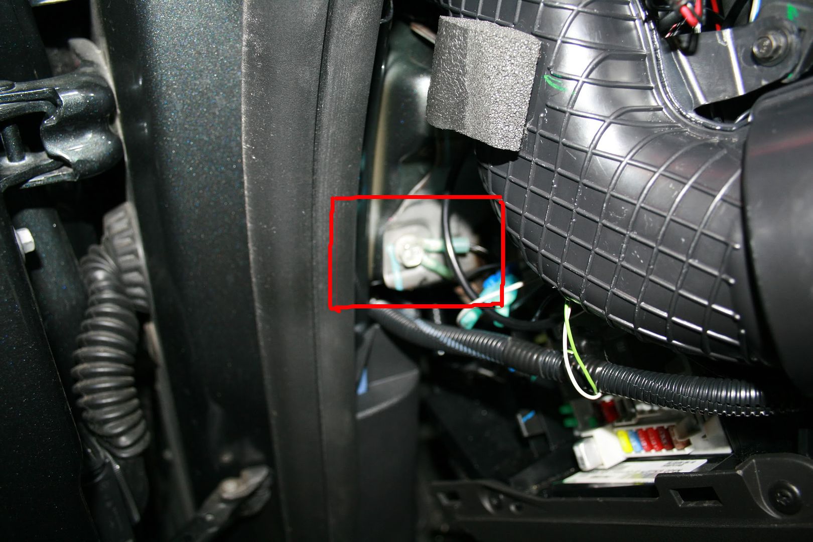
Use this for your ground.
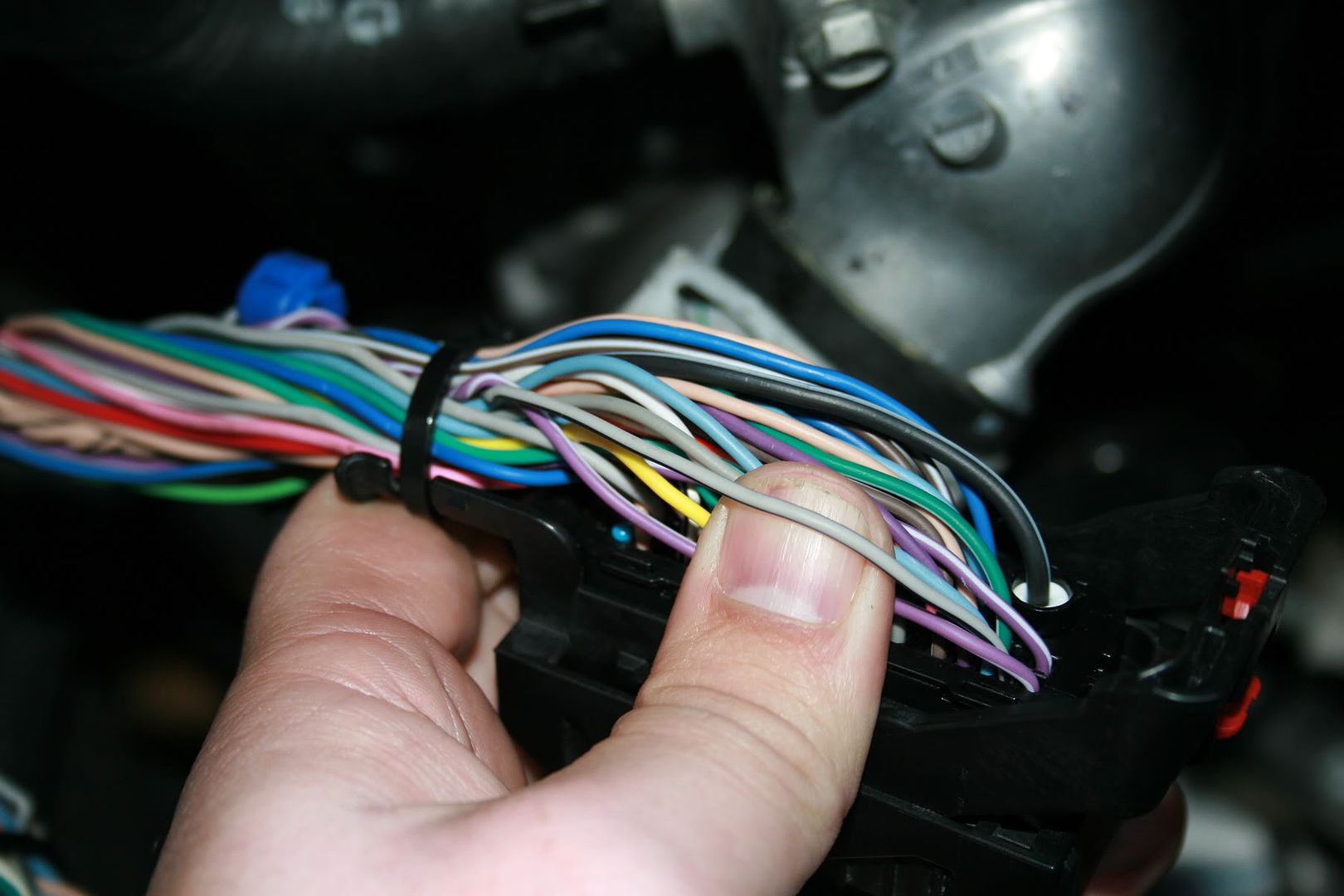
Now that we have 2 out of the 4 wires hooked up, we need to get the White, and Green wire around to the PCM.
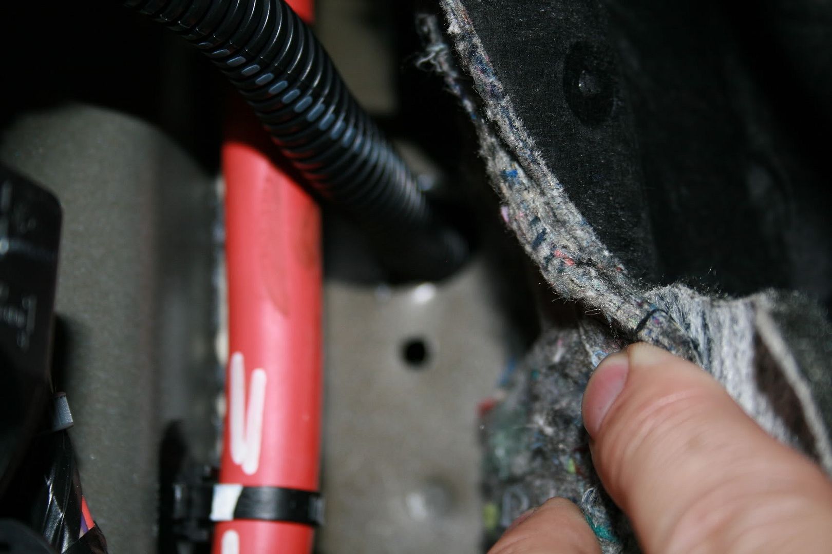
You will need to get the 2 wires into the engine compartment. I had drilled a 1/2 hole (once again from a previous install, but you will probably need to drill one here to get the wires through the firewall. unless you can find some other way.. It was just easier to drill.
To do this remove the kick plate cover, and the threshold cover. Using a 1/2 drill bit drill your hole.. You will need verify you aren't drilling into the brake booster, or anything else here. I would give measurements, but don't wont to be held accountable if they are different for you. YOU WILL NEED TO MEASURE OUT WHERE A CLEAR SPOT IS.
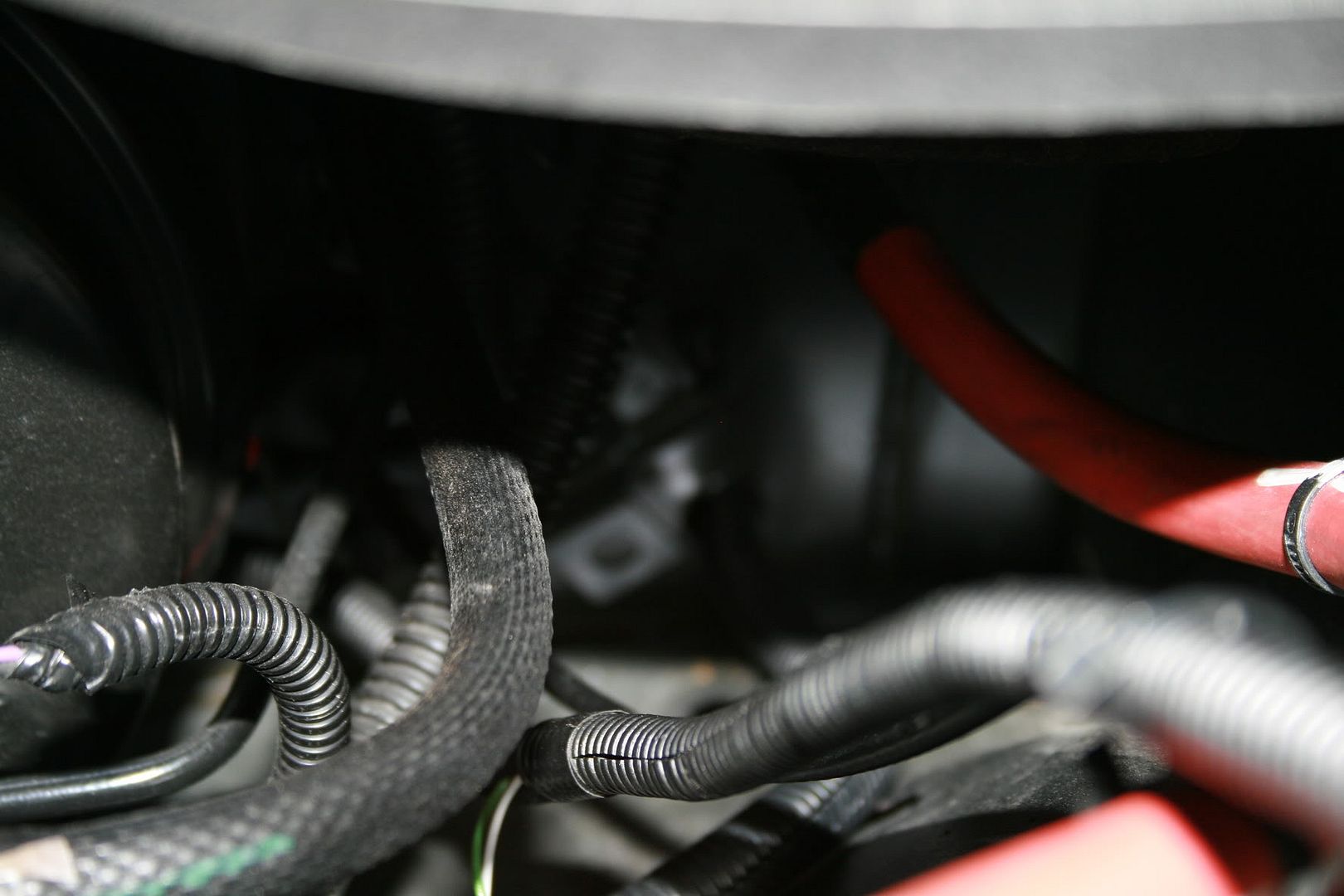
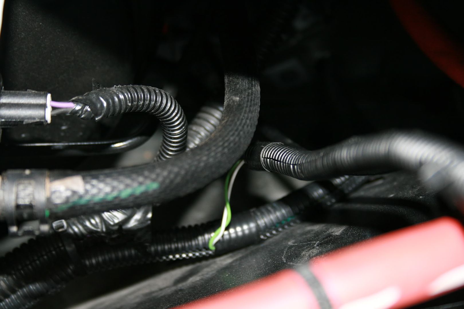
Once your hole is drill using some wire loom snake the to wire through the hole, concealing the wire as much as possible to make a nice clean setup.
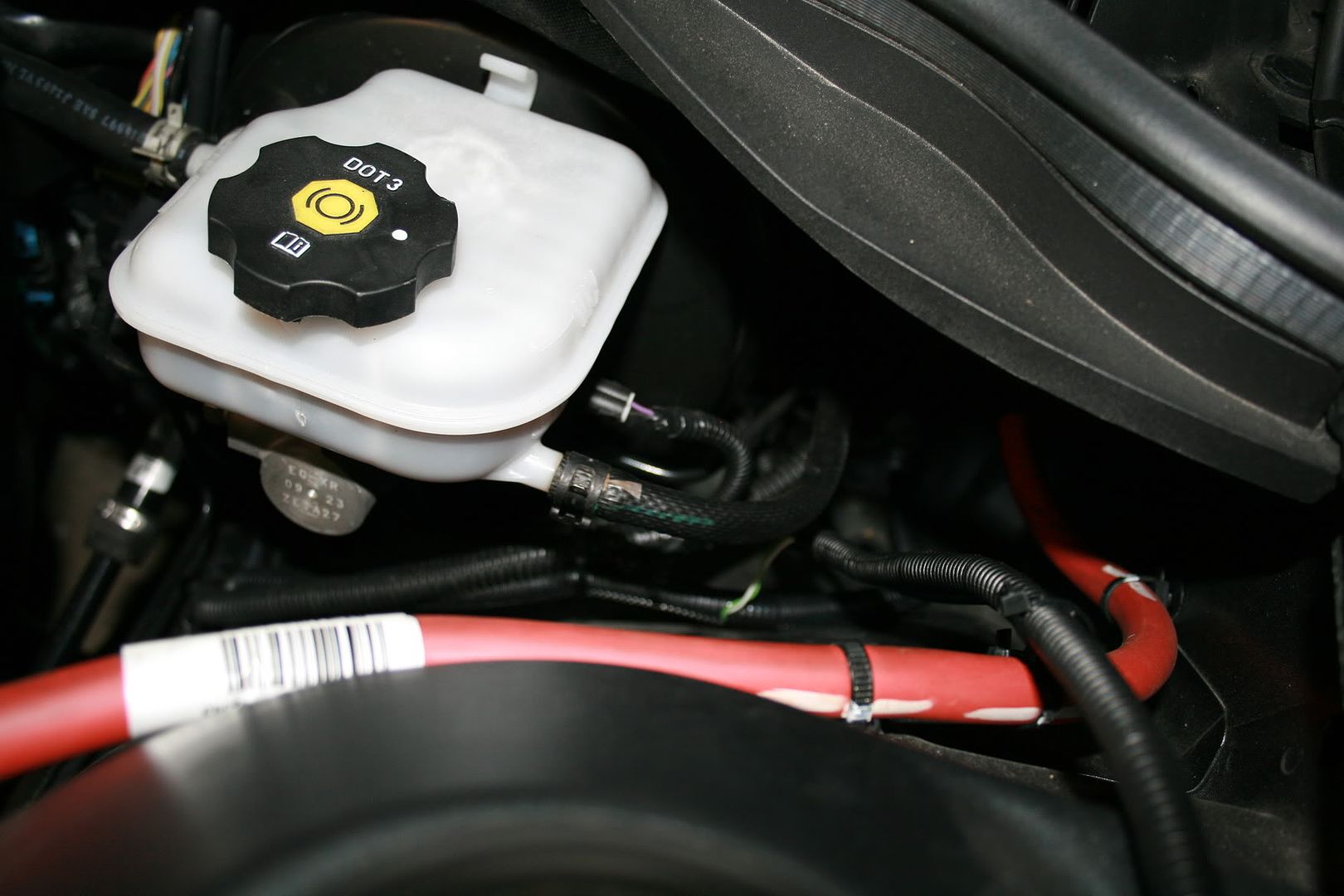
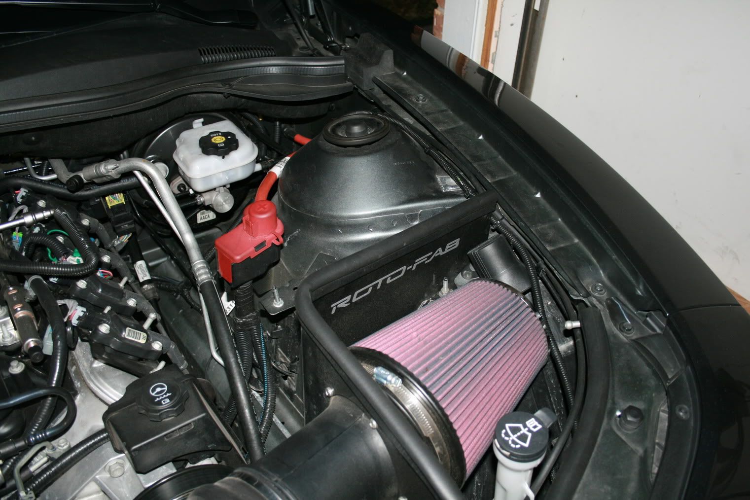
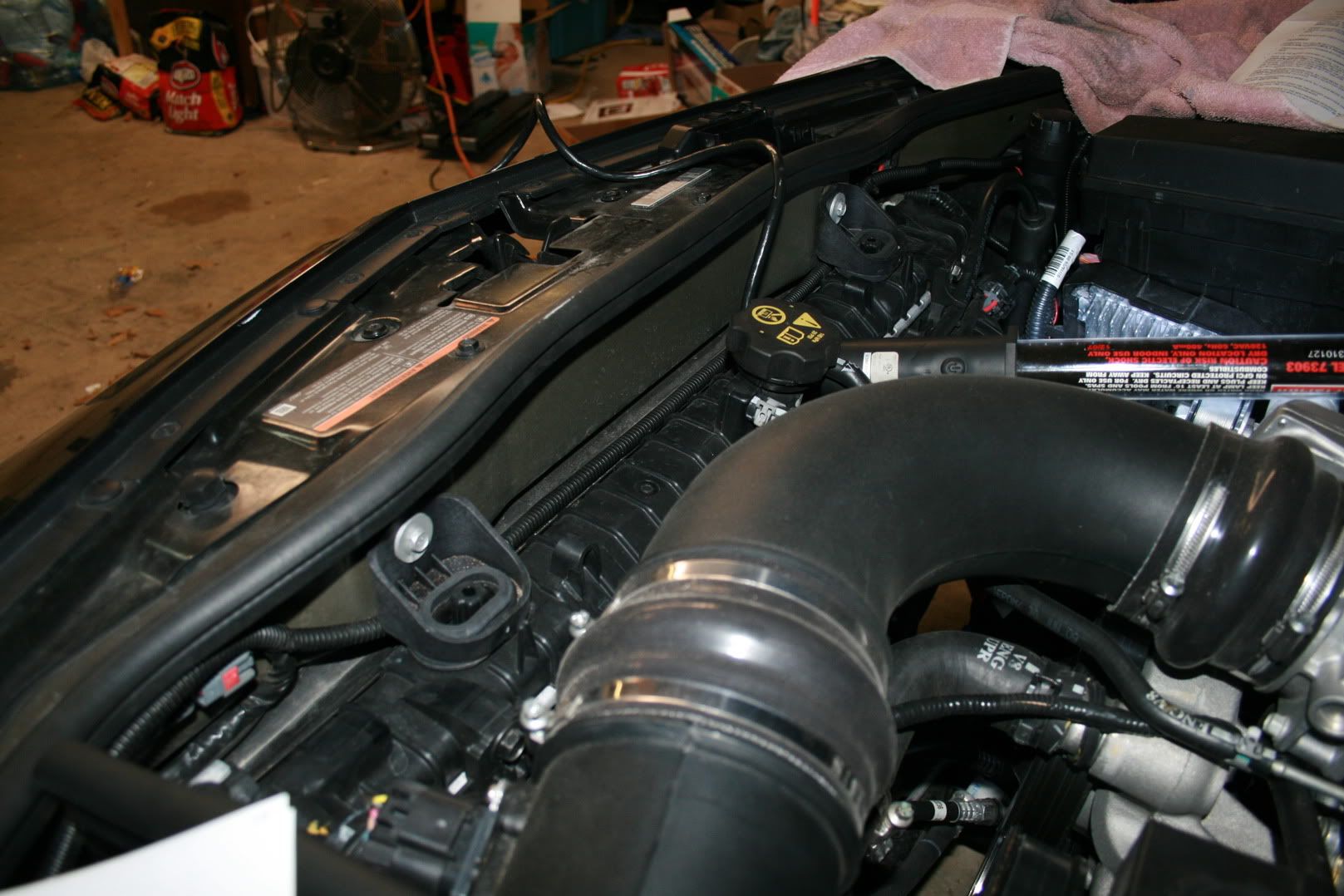
From here I took the 2 wires around the driver front of the car. along the radiator, and out right past the radiator fluid level check cap.
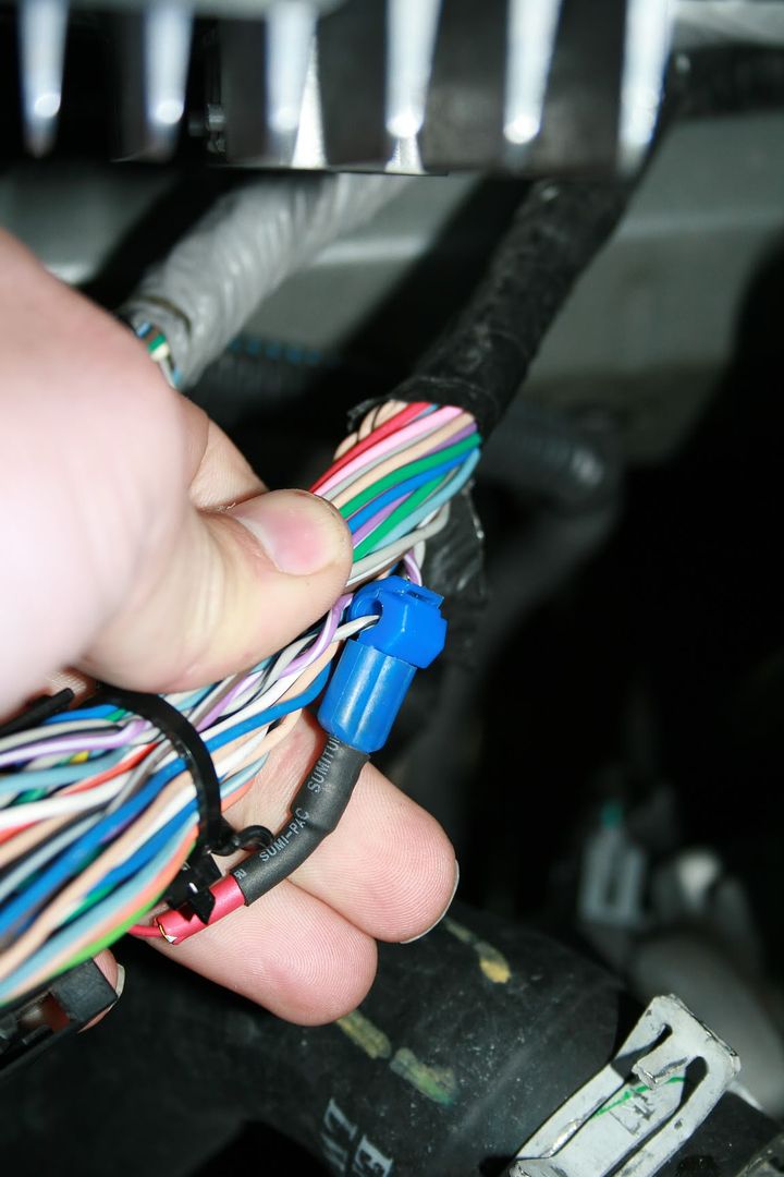
This is where your excess red, and black wire comes in. You will need to splice on some additional wire. If you want you can go obtain some more Green and white wire, but I felt the black and red was sufficient, and just used it. Remember if you do use the red, and black wire, remember which color you spliced together.
I spliced white with red,
and Green with Black.
Now here is where everyone is getting confused on where to hook the white, and green wire up..( if you only bought the shift light, and not the dual launch light, then you only have to worry about the green wire, you wont have a white wire)
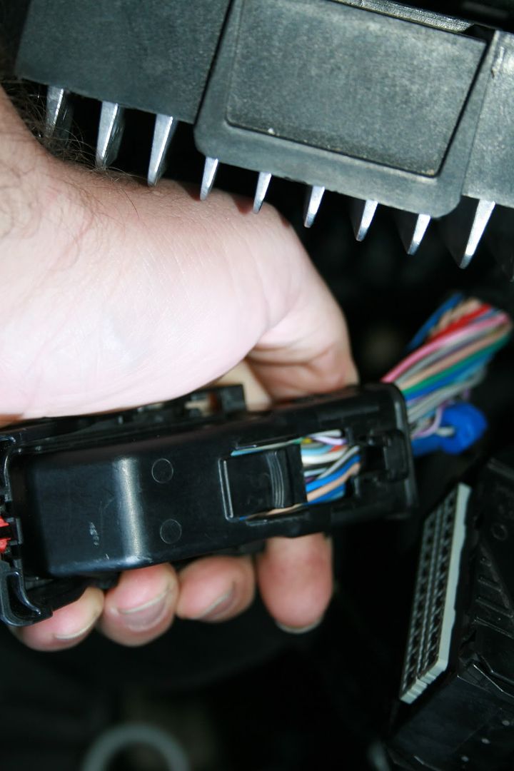
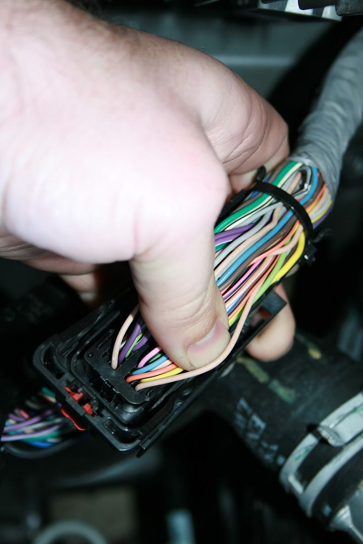
Now once you have the 2 wires over to the PCM, you need to remove the 2 connectors. Here is a nice little video on how to do this.
http://www.motorz.tv/blog/1330/how-t...-chevy-camaro/
Once you have the connectors off.
the black Connector is X1,
and the Gray Connector is X2
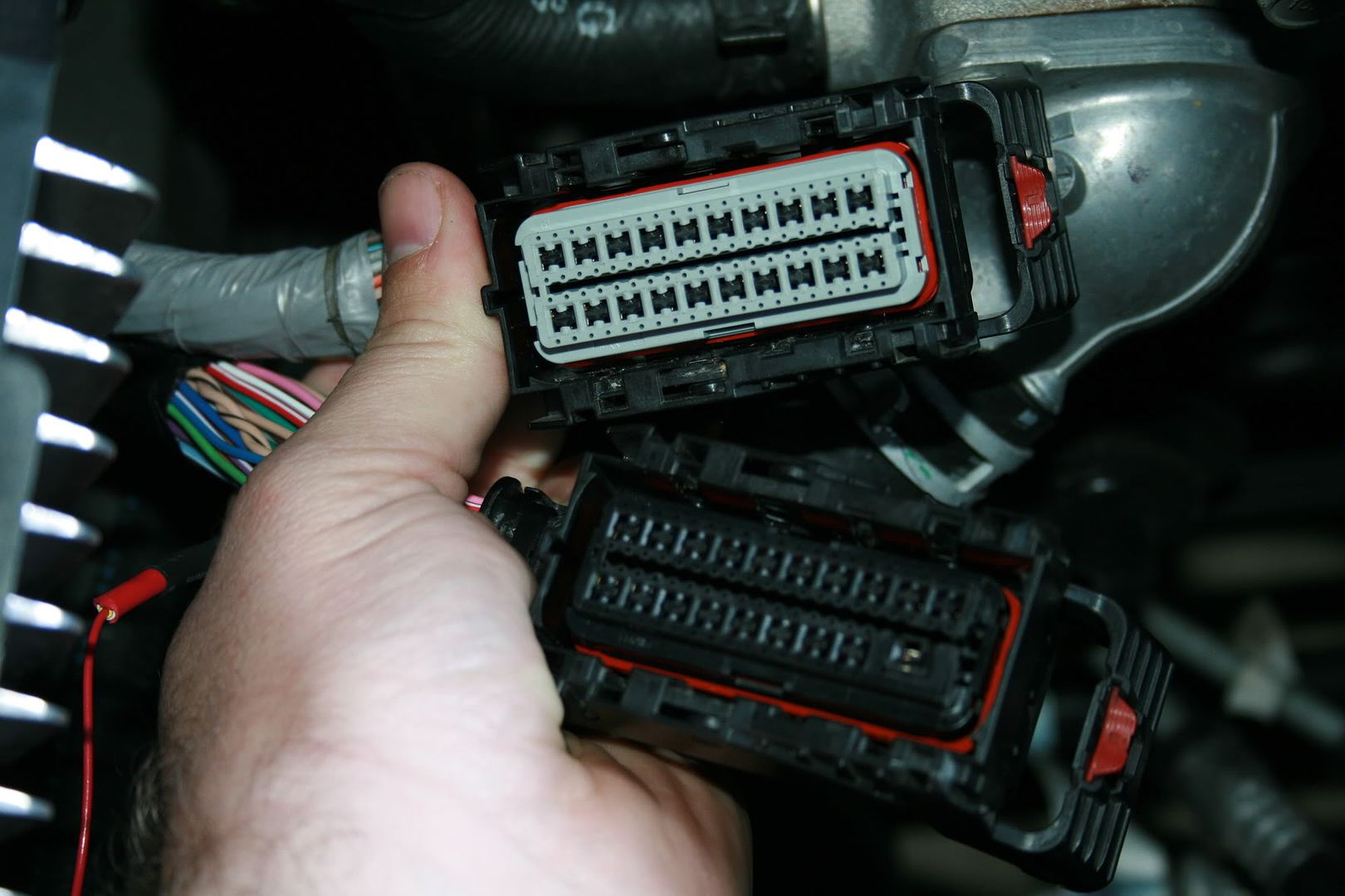
Remove the black plastic cover. it is held on by a tab on either side of the connector.
Now take X1, what you are looking for is Pin 71. It is a Gray w/black stripe wire.
This is your VSS Signal wire.
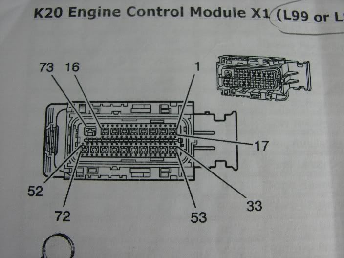
Using a 16-14 gauge T-Tap attach your white wire to here.
Now for the X2 Connector You are looking for Pin 20. It is a tan wire. Located here.

repeat what you did for X1 here.
Almost done.
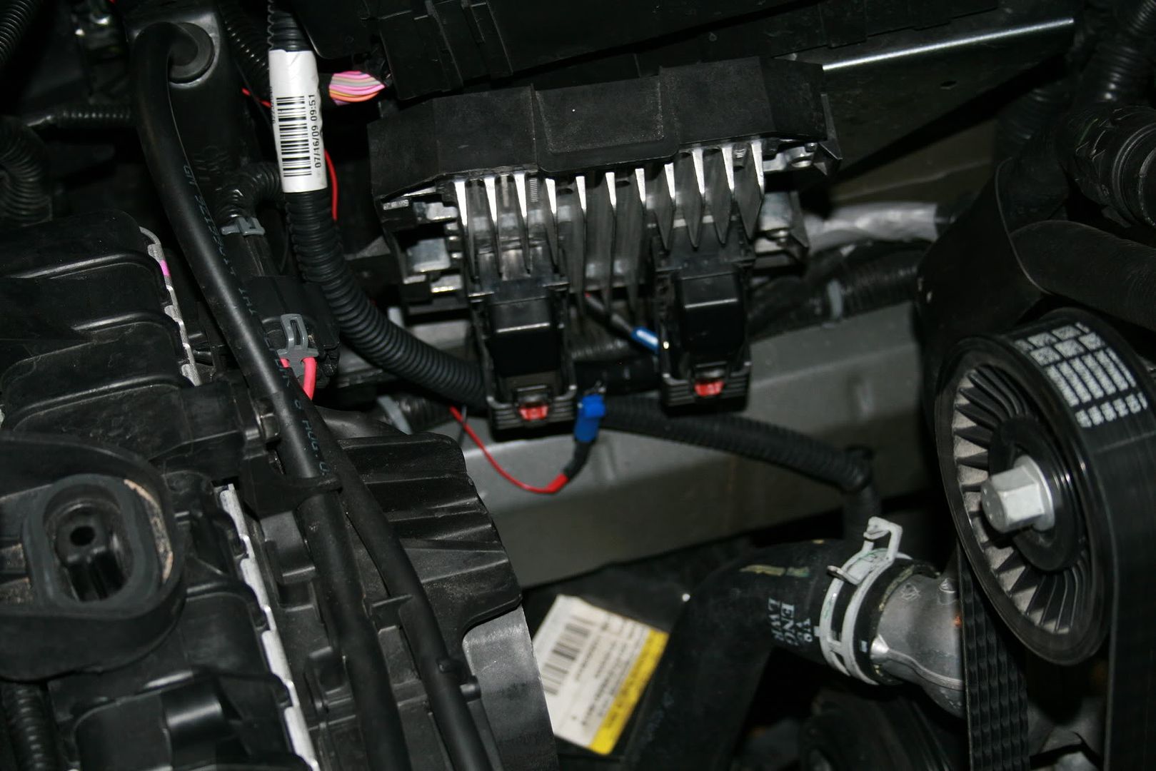
replace the 2 black plastic covers on the connectors. Then reinsert the connectors into the PCM.
Once everything is back together is should look similar to this.
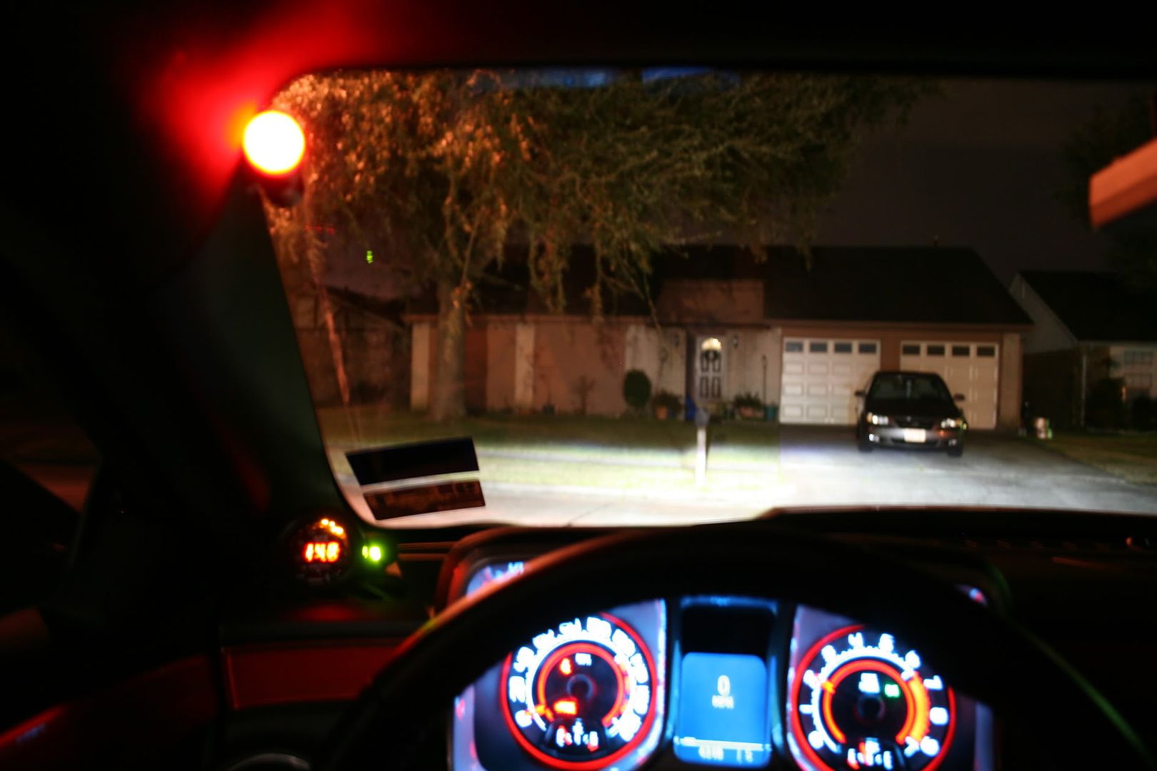
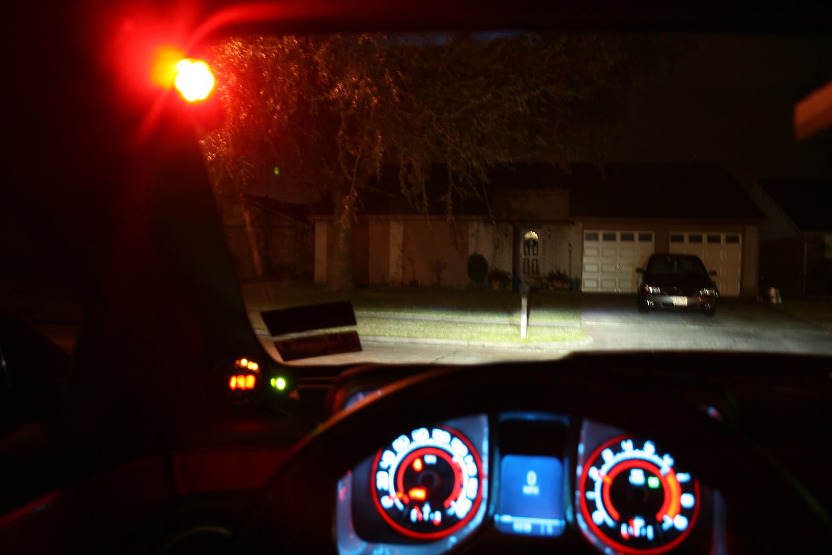
I would advise using the covers supplied with the light.. as at night the Red LED lights are very blinding without the cover.. with the cover on it is still very visible but doesn't light the whole cab of the car up.
couple of pics
with the cover light on
With out the cover on
I hope this helps everyone is trying to figure out what wire goes where, with installing a Raptor Shift Light.
Daniel.....
