RGB_Halos.pdf
So, youve decided you want multi-color halos without the absurd price. Ever wonder what makes the various products on the market tick? After a bit of looking, I found that its nothing more than a controller, a few resistors and the right LED. A little more looking found that you can buy the stuff needed for fairly cheap. While the method I will detail does involve baking your lights, Ive done three sets and theyve all survived, but I do believe that with enough determination, the JDP method will work as well. The price, not including the adhesive sealant, wire, tape and butt connectors is about $16.45 all shipped to your door and ready for assembly.
Things you will need:
3W 4-Pin RGB LED w/ Platine base (x2 and available on eBay)
RGB LED Controller (available on eBay)
10W 10 Ohm Resistors (x3 and available on parts-express.com)
A Tube of Adhesive Sealant (I prefer the type that fit in a caulking gun as theyre much easier to use and make sure it for use with plastic. Most silicone based ones are and I found work best)
Soldering gun/Solder (If you are one of the few that dont know how to solder, watch a few videos and get to practicing.)
Wire (smaller the better, I used 18ga)
Wire Crimpers/Butt Connectors
Small zip ties (The black ones tend to hide better.)
Double Sided Sticky Tape (Just a little is needed)
A Drill with about a 3/8 bit (doesnt have to be exact, just has to create a hole large enough for wires to pass through)
Removal of lamp assemblies:
(FYI there are 4 10mm bolts on each side, not 3. The fourth one is close to the side marker. There is also a 7mm near the side marker as well.)
Disassembly of lamp assemblies:
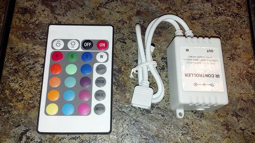
RGB LED Controller from eBay
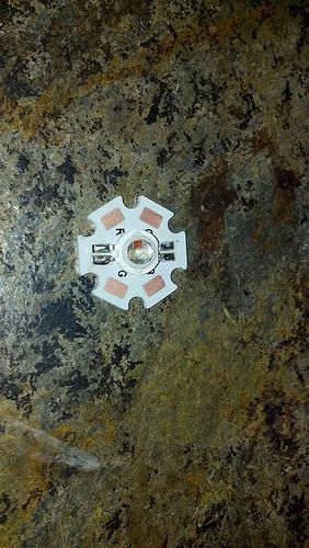
RGB LED, again found on eBay
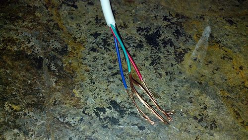
Start by cutting the end off the controller and strip the wires back a ways. (The little black part is the optic the IR remote communicates with, leave it alone.)
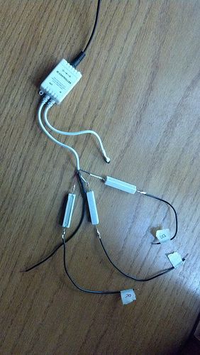
Solder or otherwise connect the red, green and blue wires to a 10W 10 Ohm Resistor. Connect the black wire to a length of wire that is easier to work with/connect to. Be sure to mark which color each wire is at its end. Also be sure to use plenty of electrical tape here. I wrapped each connection then wrapped them all together as it becomes easier to hide once installed.
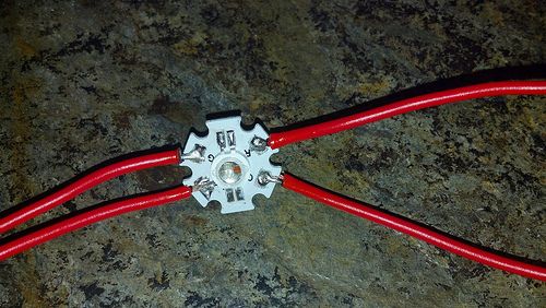
Solder wire to each RGD LEB. Each wire controls a color with the fourth giving it power. For reasons of simplicity, I used a length of about 4 feet per connection on the one for the drivers side. I used about 18 for the one on the passengers side. Be sure to solder them in the directions shown above. That way the wires will be out of the way and go on each side of the heat sink. Dont forget to label which color is which at the end of the wire!
At this point, youre ready to throw your costly assemblies into the oven!! Take a breath and watch the videos a couple times. Remember, 220 degrees for 20 minutes. A minute or two longer does make it easier to open, but as with this whole DIY, do so at your own risk. Ive now done three sets. Its really not that bad once you get the first one in and can get yourself to stop staring through the little window with the light on.
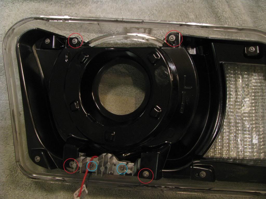
Once inside, and after you unplug the only plug that connects the lens from the rest of your assembly, there are only six torx screws you need to concern yourself with. The four in red secure the halo to the assembly. The two in blue secure the heat sink to the halo.
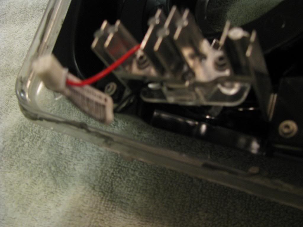
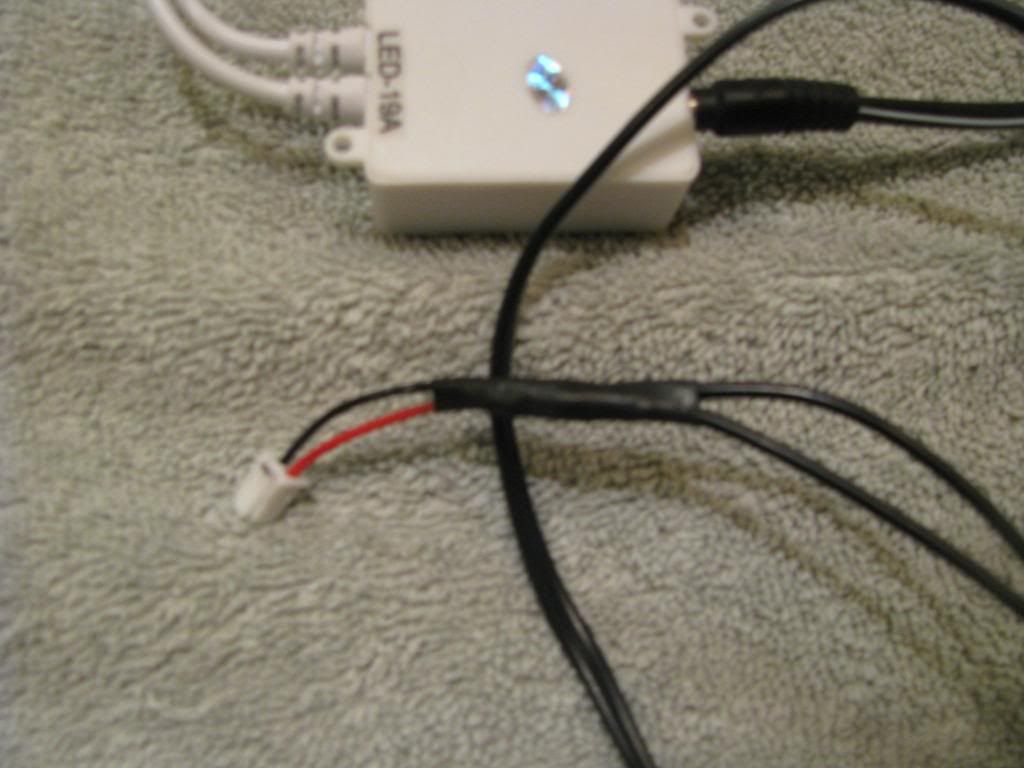
Sorry for the bad picture. This is the plug in that holds the lens to the assembly. It is also the plug for the weak factory white LED that powers the halo. Cut the end of one off and connect the positive and ground wires to the stripped power/ground wire of your controller. This will later plug back into your factory harness inside the assembly and power your halos on using the factory switch/auto lamps on function/any aftermarket harness to run your halos with your drl/fogs.
As I am very unoriginal, I stole the basis for this idea from Ofer (2SSRS). Shiny side down I wrapped the portions of the halo that arent able to be viewed with tin foil.
I then tightly covered the foil with electrical tape. No sense wasting light that can be better reflected to viewable area.
If youre not sure of the viewable area, place the halo back inside the lens. There are raised areas that block the areas wrapped in foil/tape.
Next is the installation of the RGB LED. Note, the bulb protrudes more than the factory one. Meaning the two screws that hold the heat sink onto the halo DO NOT TIGHTEN ALL THE WAY DOWN. This will destroy the LED. Simply snug them in place. I also use a small dab, and I do mean small, of super glue to hold the LED in place against the heat sink. If you wired your LED like I did mine, it should go in place with minimal effort as the wires will be on either side of the heat sink.
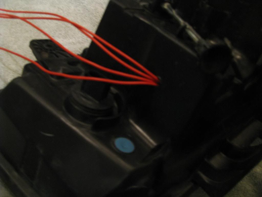
Now, simply drill a small hole and run your wires out.
Dont forget the plug for the power. It attaches to the same plug that the factory LED was plugged into, the one you had to detach to completely separate the lens from the assembly. Run it through the same hole as the wires leading out.
Almost done. Once both RGB LEDs are installed and the wires are ran, its time to button things up. Use your adhesive sealant to re-affix your lens into place on the assembly. Also, use a dab on the wires/hole that you drilled into the housing. Now for the hard part. Let your assemblies sit for whatever amount of time you can take to allow the sealant to cure.
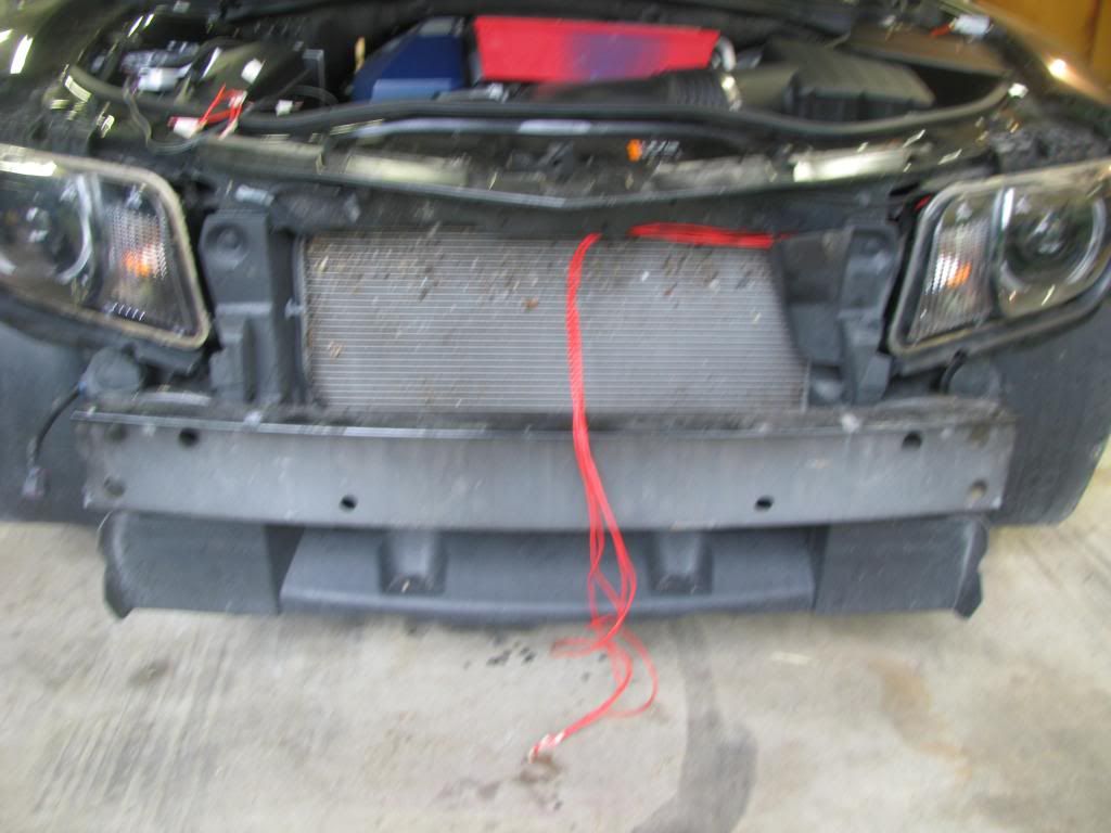
Again, sorry for the blurry pic. But, time to put it all together! I always run my wires to the passenger side, personal preference. Running the wires under the top member, use the factory holes to put zip ties through and hold those wires in place.
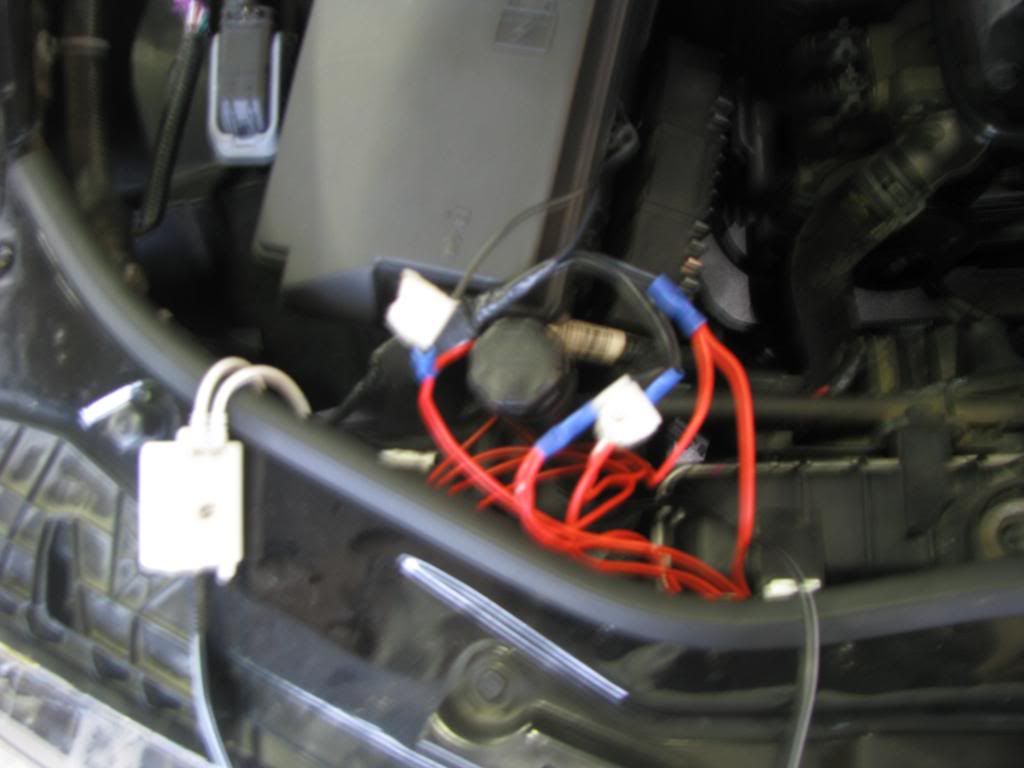
Heres where I fired the camera man. Since you were smart enough to label each wire either R, G, B or P, this is just a matter of connecting the like wires! Red/green/blue/power wires from each simply attach using butt connectors to the wires coming from your controller.
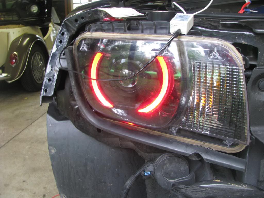
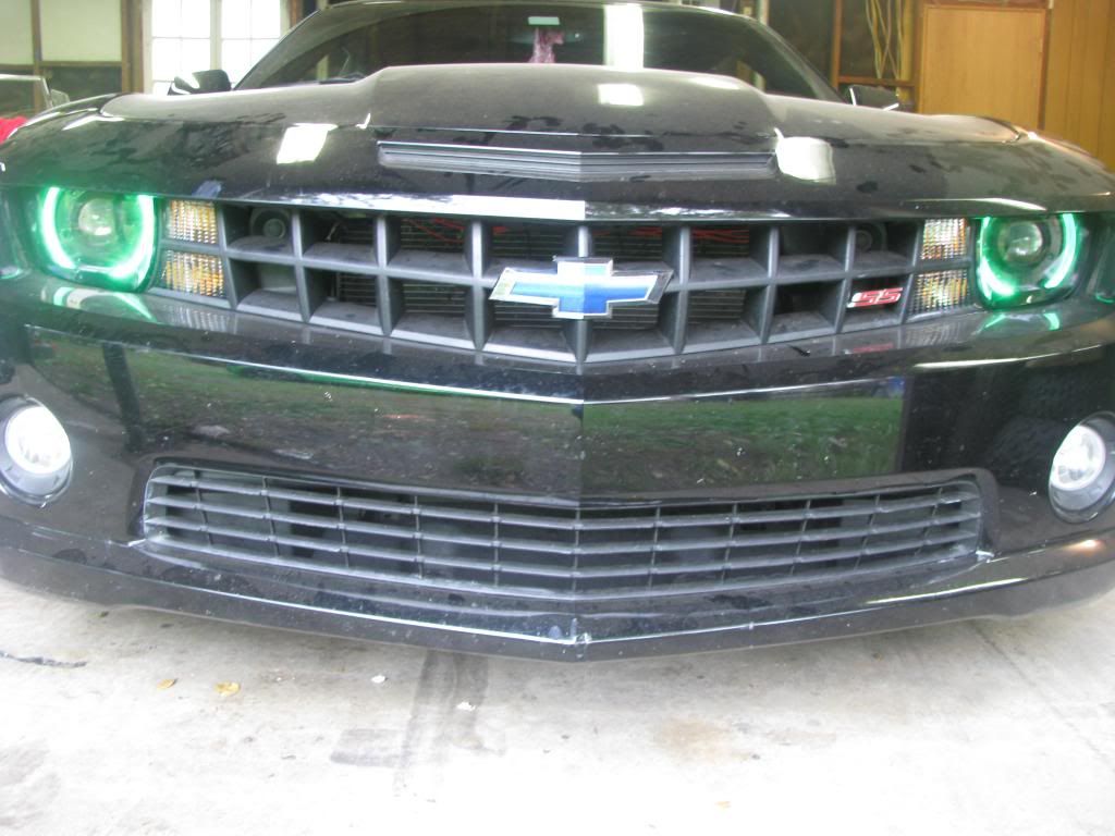
Now the part youve been dying to see, if it worked! Before I replace one screw/bolt/push pin, I test it out. All is good, moving on!
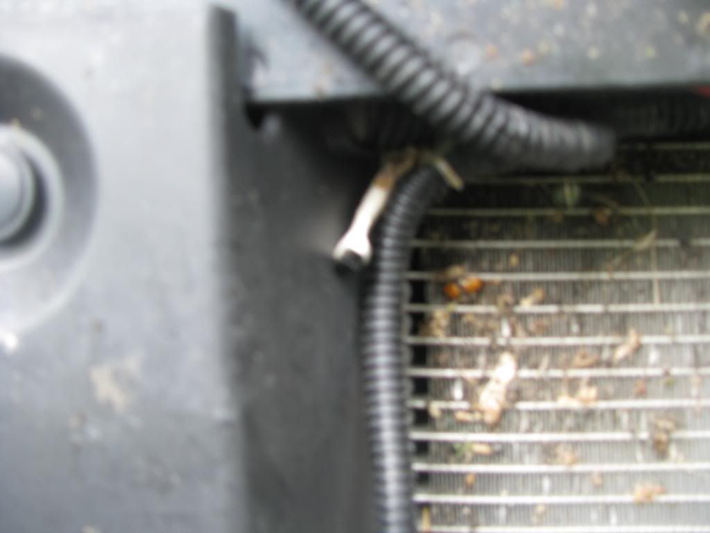
Neatly tuck your wires and use a little double back sticky tape on the back of the controller. Affix it up and out of the way on the top support bar near the radiator and run the little black eye back out the small area next to the radiator.
Now, put it all back together and start turning heads. The first time I did this, not including the time my assemblies sat curing, it took me about 3-4 hours to completely for the first time ever tear everything down and put it all back together. This last set took me a couple hours, mainly because one lens didnt want to come apart. The hardest thing to get over, for me at least, was gathering the cajones to throw my stuff in the oven. Beyond that, its not all that difficult. Enjoy!