You are browsing camaro5 

|
 06-28-2013, 10:35 AM
|
#1 |
|
It doesn't mean anything
Drives: 2011 Camaro LS Join Date: Jul 2012
Location: Wadsworth, Ohio
Posts: 85
|
N2O Control & Gauges via Bluetooth
Hi everyone!
So I just bought a Ny-Trex Kit  via the group buy over in the FI - V6 board. Instead of buying a switch-panel and gauges though, I'm going to try to make a system to control and monitor everything via an Android app and Bluetooth. In theory this should be easy using an Arduino, Relay Shield, Bluetooth Shield, and a couple sensors with linear analog outputs. If anyone has done this before PLEASE step in with advice, last thing I want to do is make a mistake while working with N20... via the group buy over in the FI - V6 board. Instead of buying a switch-panel and gauges though, I'm going to try to make a system to control and monitor everything via an Android app and Bluetooth. In theory this should be easy using an Arduino, Relay Shield, Bluetooth Shield, and a couple sensors with linear analog outputs. If anyone has done this before PLEASE step in with advice, last thing I want to do is make a mistake while working with N20...Here's where I stand: Arduino Uno (~$20) 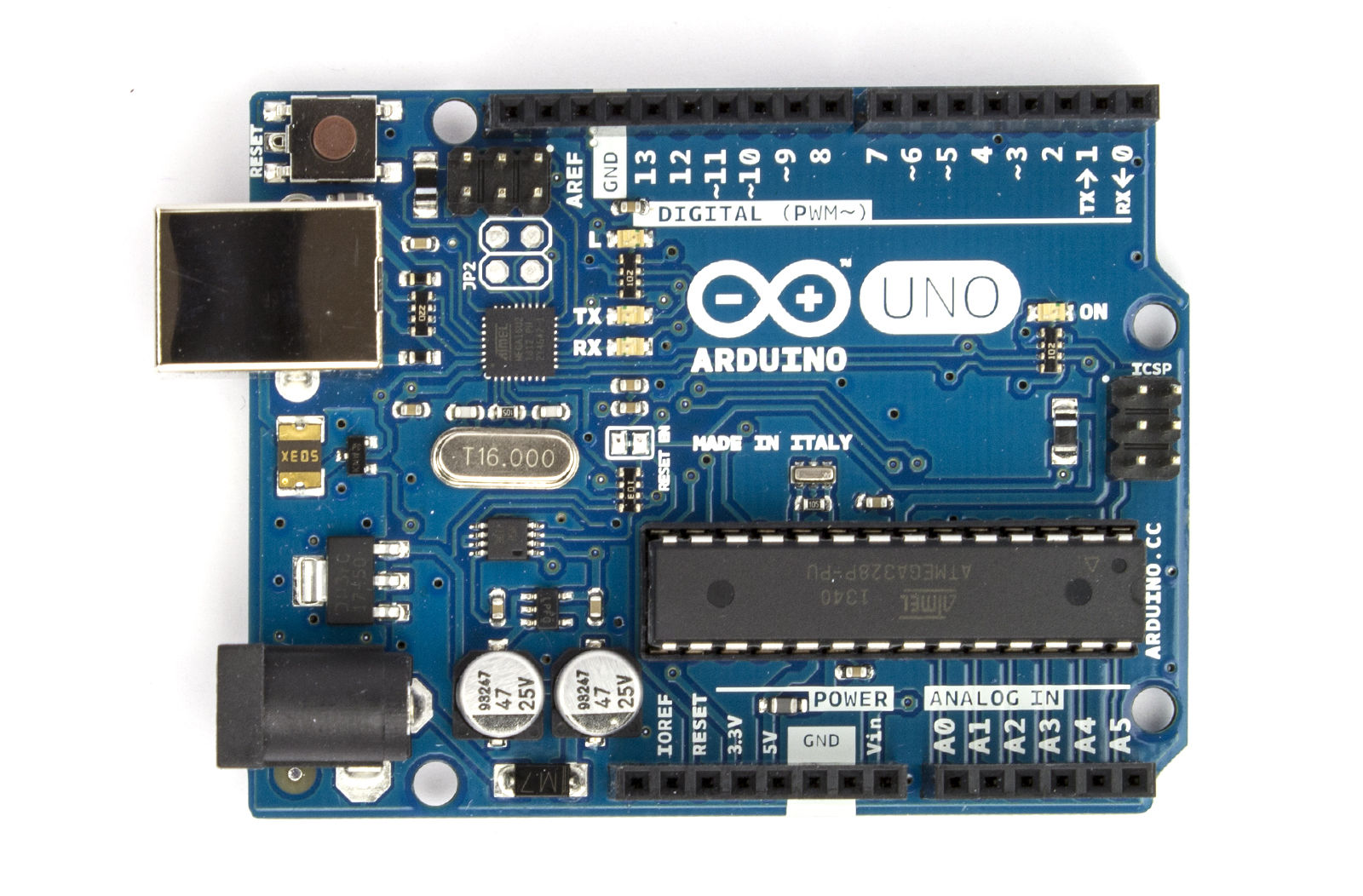 This is the brains of the project. Had one laying around that I've been trying to find a purpose for. Guess I have one for it now! Seeed Bluetooth Shield (~$23)  This is what will allow the system to be controlled via Bluetooth. In case anyone (nobody) is wondering why I didn't use a BLE shield, it's because BLE doesn't require pairing so anyone would be able to walk up to my car and turn on the Nitrous with their phone/computer. So obviously BLE is out, and with it goes control via iOS, which is why the app will be an Android app. Seeed Relay Shield v2.0 ($20)  The relays here will take the place of the switches for Arm/Disarm, Purge, and Open/Close. Had to go with the v2.0 instead of v1.0 to handle the higher Voltages and Amps of the system. I'm still a little concerned I might fry it, but if so I'll just have to make my own board with better relays. Holley EFI Pressure Sensor (~$110)  I'm planning to us this to monitor bottle pressure. Still need to make sure this actually fits though. While this is actually meant to plug into some expensive system, the wiring is rather simple: +5v, Ground, and Signal. The signal wire puts out 0.5v-4.5v in a linear relationship to 0psi - 1600psi. I should be able to just connect this to an analog-in port of the Arduino, apply a simple formula, and get PSI. LC-1 Wideband Kit (~$200) This will provide readings for the AFR gauge. Similar to the pressure gauge, it has an analog signal wire that puts out 0v-5v in a linear relationship to 7.35 - 22.39. IF ANYONE CAN RECOMMEND CHEAPER SENSORS, PLEASE DO!!!!! App Design:  This is just a rough mockup of what the app will look like. Planning to have the backgrounds of the gauge readings change from green, yellow, and red to indicate ok, warning, and bad accordingly. Also plan to have the ARM and OPEN buttons green when they are activated, while DISARM and CLOSE will be red when activated. This should allow me to see the system status with a quick glance. For future reference, I am NOT great when it comes to graphics. I can build the circuit and code the app easily, but I will definitely struggle when it comes to making the app look "cool" If anyone feels like helping when I get to that part, it will be GREATLY appreciated. Device Placement:  This is just to indicate where I plan to put the Android touchscreen device. I want the screen of the device to take up that whole area where the dash trim is. During testing, it will probably just be velcroed there. Once everything is complete though, I'll probably have someone make and enclosure for it and hardwire it in so it looks "stock" I haven't settled on an Android device yet and any suggestions are appreciated. Either a phone or small tablet will work as long as it has bluetooth. Well that's it for now. I'm waiting for the Arduino shields to arrive so I can start programming. I'll try to keep this updated for anyone who finds this interesting. Thanks!
__________________
Hmmmm..... I should probably get a fancy sig
|

|

|
|
06-30-2013, 03:43 AM
|
#2 |
 Drives: 2010 Camaro Join Date: May 2012
Location: Eagle River, AK
Posts: 28
|
Isn't this same thing minus the sensors? Just a plug n play into the ob2 port.
http://www.plxdevices.com/product_in...=GSSTBLUETOOTH |
|
|
|
|
06-30-2013, 11:11 AM
|
#3 | |
|
It doesn't mean anything
Drives: 2011 Camaro LS Join Date: Jul 2012
Location: Wadsworth, Ohio
Posts: 85
|
Quote:
Ironically though, their AFR module looks like it could be a cheaper alternative to the one I was going to get! So updated parts list: Old: LC-1 Wideband Kit (~$200) New: PLX Wideband AFR Moduel ($150) Cheaper than the one above, easier to wire, AND it never needs to be calibrated! Outputs analog signal 0v-5v in a linear relationship to 10 - 20 AFR. Big thanks to mwt18 who sold me his used one for $60! I officially have an AFR sensor. Still hope I can find a cheaper Bottle Pressure sensor somewhere.
__________________
Hmmmm..... I should probably get a fancy sig
|
|
|
|
|
|
07-01-2013, 12:19 AM
|
#4 | |
|
It doesn't mean anything
Drives: 2011 Camaro LS Join Date: Jul 2012
Location: Wadsworth, Ohio
Posts: 85
|
My Arduino parts arrived so I started that part of the project over the weekend. I somehow ordered the wrong Relay Shield, but no big deal as I can just attach the right one when it arrives.
I finished the code the Arduino will use then tested it with my computer and some LEDs. Everything seems to be working great. Here's a video of the test: For anyone interested, here are the details: The Relay Shield arrived in one piece and didn't really require any setup. The Bluetooth Shield however, was in pieces and needed to be soldered.  First thing I soldered on was the pins to connect to the Arduino. I kinda got ahead of myself though and used the wrong set of pins in one section... Here's how I originally soldered it (the wrong way):  Here's the right way:  Notice the smaller set of pins on the bottom left corner. By the time I realized I made the mistake, I had already soldered the shield headers. So unfortunately one melted a little while trying to de-solder the pins, but luckily it still works.   Finally was the pins for the transmission jumpers and the cover for the Bluetooth chip.  Here's a picture showing the position of the jumpers and switch.  The switch is down, BT_RX is jumppered to 3, and BT_TX is jumppered to 2. This is necessary for my code to work. Here's the code, it's pretty simple. Pins 4-6 are activated based on the bluetooth serial input, and each pin corresponds to a relay. Analog pin 1 is monitored for Bluetooth state, and sets all pins to low if connection is lost. The status of analog pins 2 and 3 (for the gauges) and the digital pins are sent back 20x a second. Code:
/*
BluetoothShield Code NOS.pde. This sketch allows the shield
to commmunicate over software serial using pins 2 and 3 and
trigger pins 4 - 6 based on the characters received. Output
state of trigger pins are transmitted back. Analog pin 1 is
monitored for Bluetooth Status. Analog pins 2 and 3 are also
monitored. Their values are transformed and also transmitted back.

Author: Alphonso Samano

*/


/* Upload this sketch into Arduino and press reset*/

#include <SoftwareSerial.h>   //Software Serial Port

#define RxD 2
#define TxD 3
#define ARM 4
#define PURGE 5
#define OPENER 6

#define BT 1
#define AFR 2
#define BP 3

char recvChar;
String systemState;
int btStatus;
int btTracker = 0;
int afrGauge;
int bpGauge;
unsigned long refresh;

SoftwareSerial blueToothSerial(RxD,TxD);

void setup()
{
  Serial.begin(9600);
  pinMode(RxD, INPUT);
  pinMode(TxD, OUTPUT);
  pinMode(ARM, OUTPUT);
  pinMode(PURGE, OUTPUT);
  pinMode(OPENER, OUTPUT);
  setupBlueToothConnection();
}

void loop()
{
  CheckBTStatus();
  if (btTracker >= 5)
  {
    CheckSwitches();
    SendSystemState();
  }
}

void setupBlueToothConnection()
{
  blueToothSerial.begin(38400); //Set BluetoothBee BaudRate to default baud rate 38400
  blueToothSerial.print("\r\n+STWMOD=0\r\n"); //set the bluetooth work in slave mode
  blueToothSerial.print("\r\n+STNA=SeeedBTSlave\r\n"); //set the bluetooth name as "SeeedBTSlave"
  blueToothSerial.print("\r\n+STOAUT=1\r\n"); // Permit Paired device to connect me
  blueToothSerial.print("\r\n+STAUTO=0\r\n"); // Auto-connection should be forbidden here
  delay(2000); // This delay is required.
  blueToothSerial.print("\r\n+INQ=1\r\n"); //make the slave bluetooth inquirable
  delay(2000); // This delay is required.
  blueToothSerial.flush();
}

void CheckBTStatus()
{
  btStatus = analogRead(BT);
  if (btTracker == 0 && btStatus >= 5)
  {
    btTracker = btStatus;
    Serial.print("Bluetooth Connection ESTABLISHED");
    delay(2000); // This delay is required.
    refresh = millis();
  }
  if (btTracker >= 5 && btStatus == 0)
  {
    btTracker = 0;
    Serial.print("Bluetooth Connection LOST");
    digitalWrite(ARM, LOW);
    digitalWrite(PURGE, LOW);
    digitalWrite(OPENER, LOW);
    delay(2000); // This delay is required.
  }
}

void CheckSwitches()
{
  if(blueToothSerial.available()) //check if there's any data sent from the remote bluetooth shield
  {
    recvChar = blueToothSerial.read();
    switch (recvChar)
    {
      case 'A':
        digitalWrite(ARM, HIGH);
        break;
      case 'D':
        digitalWrite(ARM, LOW);
        break;
      case 'P':
        digitalWrite(PURGE, HIGH);
        break;
      case 'F':
        digitalWrite(PURGE, LOW);
        break;
      case 'O':
        digitalWrite(OPENER, HIGH);
        break;
      case 'C':
        digitalWrite(OPENER, LOW);
        break;
      }
      blueToothSerial.flush();
    }
}

void SendSystemState()
{
  if (millis() - refresh >= 50UL)
  {
    afrGauge = analogRead(AFR);
    bpGauge = analogRead(BP);
    blueToothSerial.print('{');
    blueToothSerial.print(afrGauge);
    blueToothSerial.print(',');
    blueToothSerial.print(bpGauge);
    blueToothSerial.print(',');
    blueToothSerial.print(digitalRead(ARM));
    blueToothSerial.print(',');
    blueToothSerial.print(digitalRead(PURGE));
    blueToothSerial.print(',');
    blueToothSerial.print(digitalRead(OPENER));
    blueToothSerial.print('}');
    blueToothSerial.print('\r');
    blueToothSerial.print('\n');
    refresh = millis();
  }
}
That's all for now. Next step is the Android app.
__________________
Hmmmm..... I should probably get a fancy sig
Last edited by mercraus; 07-01-2013 at 01:09 AM. |
|
|
|
|
|
07-06-2013, 06:36 PM
|
#5 | |
|
It doesn't mean anything
Drives: 2011 Camaro LS Join Date: Jul 2012
Location: Wadsworth, Ohio
Posts: 85
|
Here's a video to show progress on the Android app. It's not linked to the Arduino yet, but I wanted to get some feedback on the design. Let me know what you think and feel free to provide some suggestions. I'll post the code once it's done.
__________________
Hmmmm..... I should probably get a fancy sig
|
|
|
|
|
|
|
|
|
 |
| Tags |
| bluetooth, gauges, n20, nos, switches |
|
|


