Step 3:
First we are going to run the YELLOW Wire (RPM Input) to the first ignition coil. You will be getting your signal from the Purple Wire (Pin C shown in diagram below- IC1 Control). I recommend cutting the electrical tape back before you splice into the wire to make it easier to hide. Solder and heat shrink or use heat shrink crimp connects to join wires and then re-tape harness.
I could not get a good picture of the harness in my car due to a shift light that was installed on the same coil previously and the wiring was not up to par so I removed it to install at a later date and used a new coil harness so the wire is a different color. To save the confusion here is a picture of Ignition Coil 1 thanks to Moly1983 from the Camaro 5 forums:
***[If you are pinning the Yellow RPM Input wire to the ECU you will use pin X2-70 ]***
Step 4:
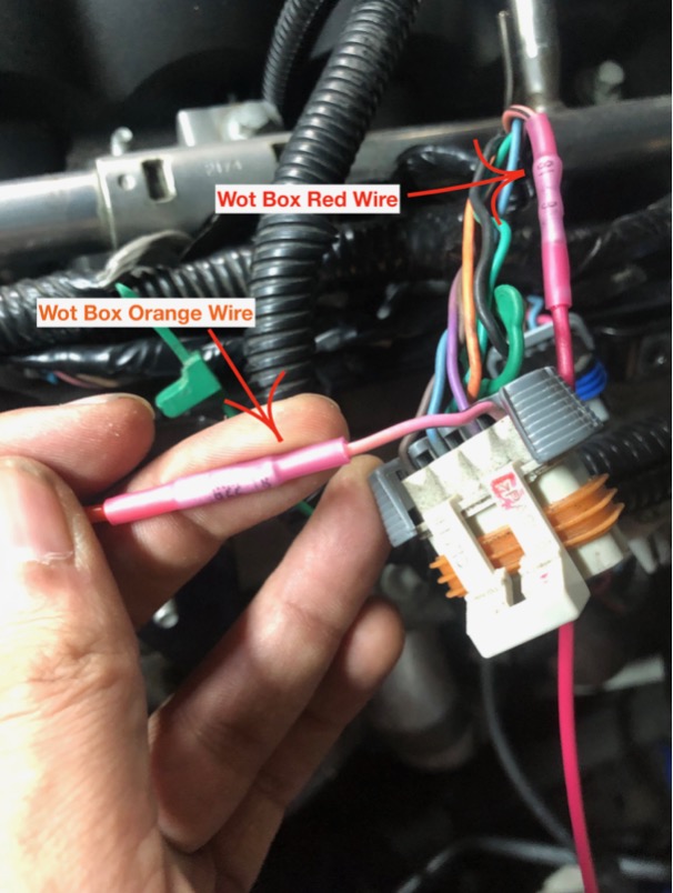
Now we are going to wire up our Ignition Power wires (RED/ORANGE wires) to the PINK/BLACK wires that supply power to each bank of ignition coils. Peel back some of the electrical tape from the ignition coil harness on both the passenger and drivers side of the vehicle and then split the pink/black wire from the harness (you can cut it back further I just know I have a project coming up in the near future that will require me re-wiring everything anyway so this worked perfectly for demonstration purposes):
At this point you are going to want to route your RED/ORANGE wires for the cleanest install so make sure you measure twice and cut once. Split the RED and ORANGE wires so you can run one of each color to both passenger and driver side ignition coils. Once you cut your wires you can now solder or connect the RED/ORANGE wires to the PINK/BLACK wires we split at the ignition coil harness.
**Make sure you have the ORANGE wire going towards the coil packs and the RED wire going towards the ECU as shown below**
 **Remember you are going to want to do this on both sides and then join each side together to your main splice. Main Splice shown below..**

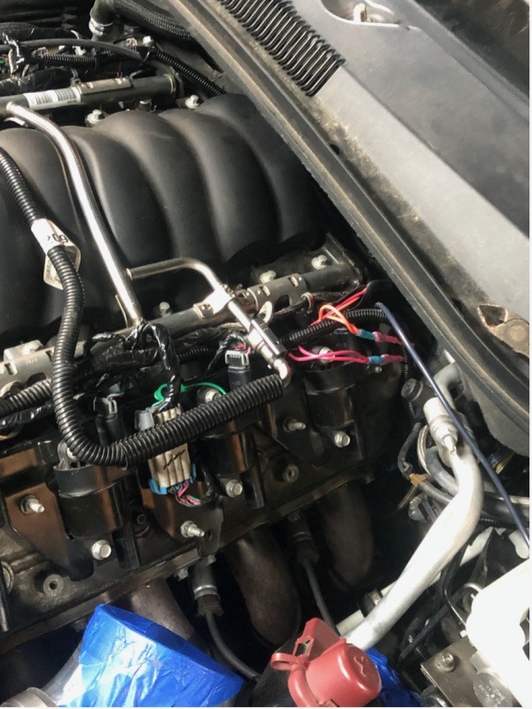 **Above Picture Shows RED/ORANGE wires from each Ignition Coil Harness to the main ORANGE/RED wire feed from the WOT BOX**
Now you are going to want to clean everything up under the engine bay. Finish taping and securing any electrical connections making sure to keep them away from any heat sources or areas where they may experience chaffing due to vibration. Use zip ties and wire loom where applicable to help hide and route your wires. You are now ready to move on to the next step!
***IMPORTANT: The RED/ORANGE wires for the ignition power MUST be tapped into the PINK/BLACK wires at the Ignition Coil harnesses. You can not tap these wires in at the fusebox because the fusebox provides power to the ignition coils and injectors on the same circuit***
__________________
Some weird snail with a belt on it
 |
| Tial Q Bov
| CCP Jam Cam
| Stainless Works 1 7/8" Headers to Custom 3" Exhaust
| Alky Control Dual Nozzle
| ProMeth Trunk Mount Tank
| Melling Oil Pump
| DSX Aux Pump
| id1050x Injectors
| McLeod RXT w/ Monster Billet Release Bearing
| ZL1 3.73 Rear Diff
| BMR Delrin/Poly Diff Bushings
| DSS 1-Piece Aluminum Driveshaft
| ZL1 Axles
| Metco Driveshaft Loop
| BMR Adjustable LCA's, TA's, Toe Rods
| BMR Adjustable Sway Bar w/ Fe3 End Links
| Mickey Thompson 305/35-20 Street S/S Drag Radials
|