I can't resist helping out my fellow car guys, so here goes...
The parts you need are:
2x Directed Electronics (DEI) 8616 relays (got mine on amazon)
3x 1N4004 diodes (radioshack has 'em)
1x 2N3904 transistor (also stocked at radioshack)
1x in-line fuse (4A)
1x switch (your choice.. just no momentary switches.. the cruise cancel button is your momentary switch!)
~10 ft. of 18 gauge wire (exactly how much depends on where you locate your switch)
1 pack of wire taps (18-22 ga)
1 pack of butt connectors (18-22ga)
1 pack of ring terminals (18-22 ga)
Here's a pic of the components:
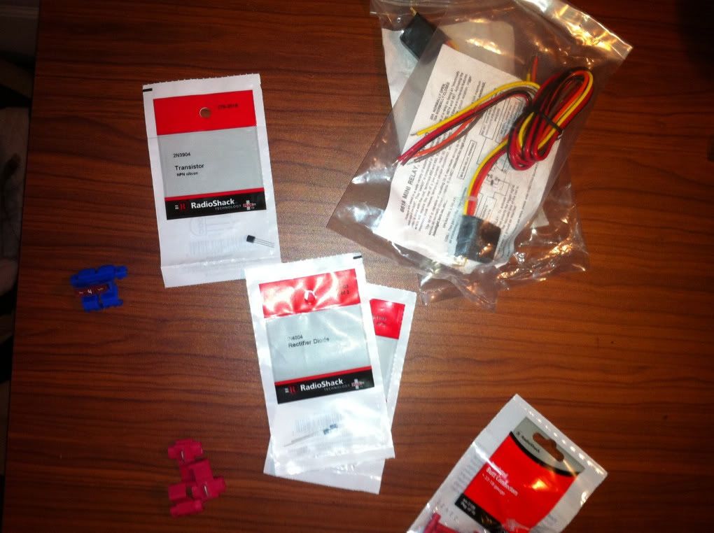
Close up of the prewired relay with wire color code:
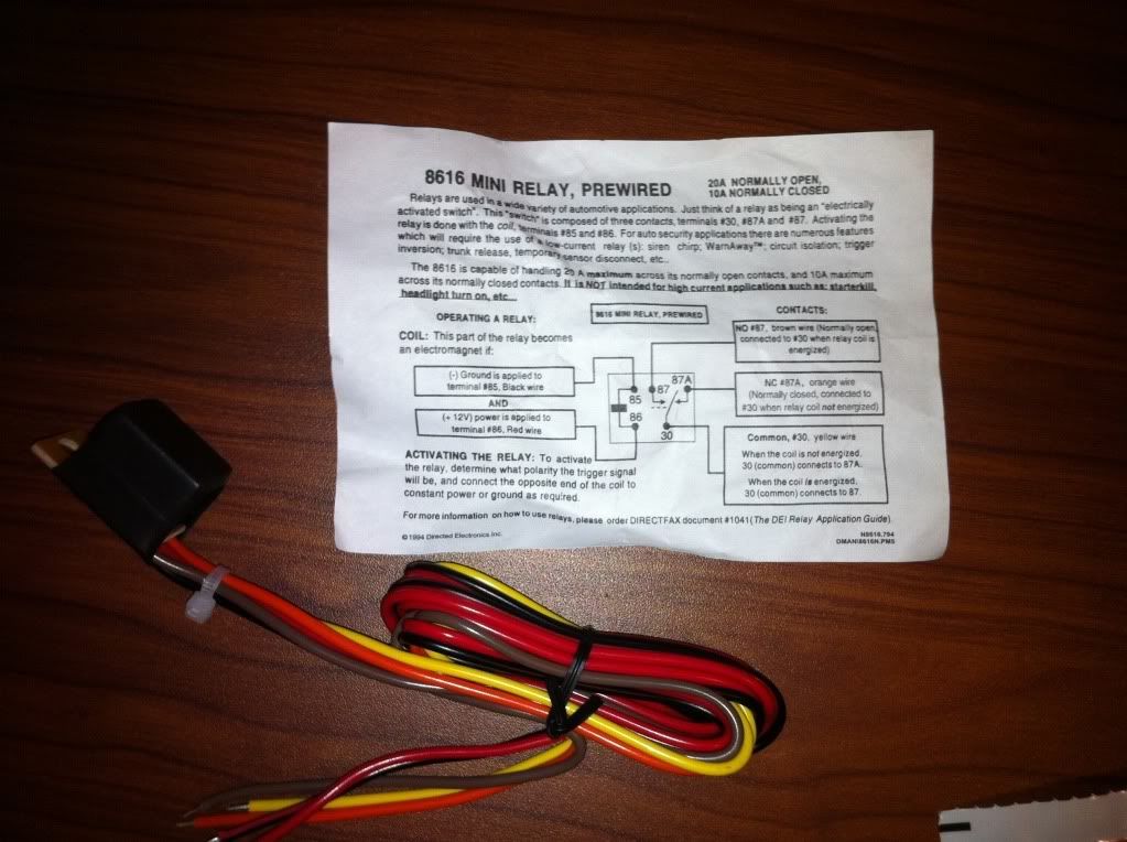
The orange wires are not used in this application, so just cut them off and tape the ends.
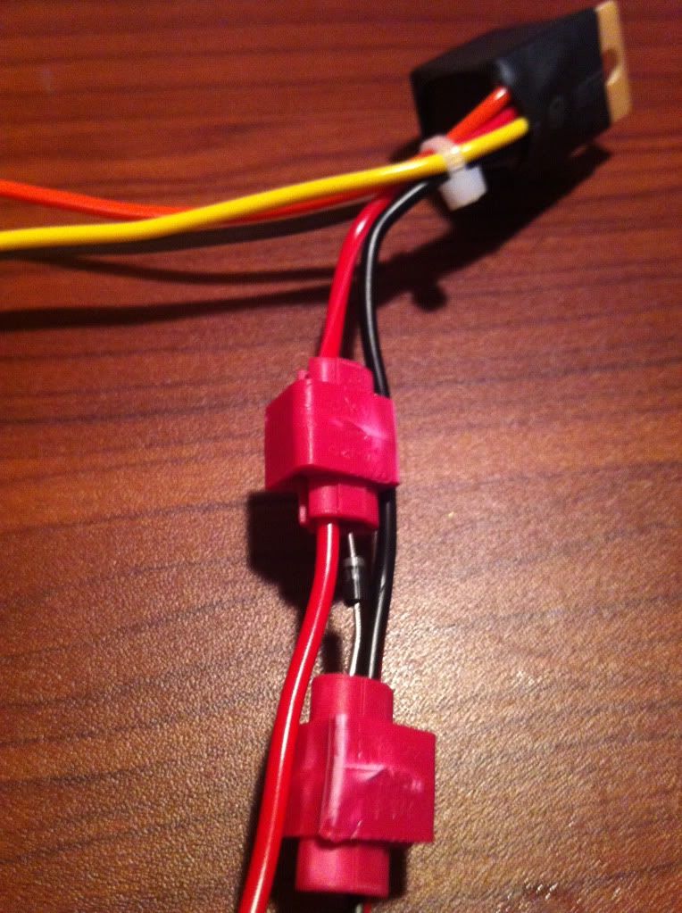
My soldering skills are horrible, so I used wire taps to place the diodes across the relays and then wrapped it up with tape. Here's a pic before taping it up:
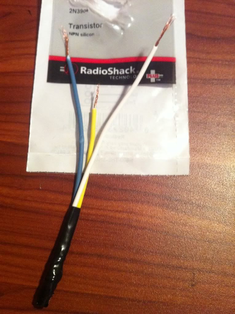
Next, is the transistor. The little bugger has 3 pins on it (C,B, and E) and they aren't all that flexible and break easily so take your time and carefully solder or otherwise connect them to some lead wires (different colors on the lead wire helps identify which pin is which). Then wrap it up in tape to secure. Here's that pic:
Now you're ready to build the circuit...Print out the diagram in my earlier post and label the different color wires on the print out. Then just use butt connectors and wire taps to join.. Here's mine:
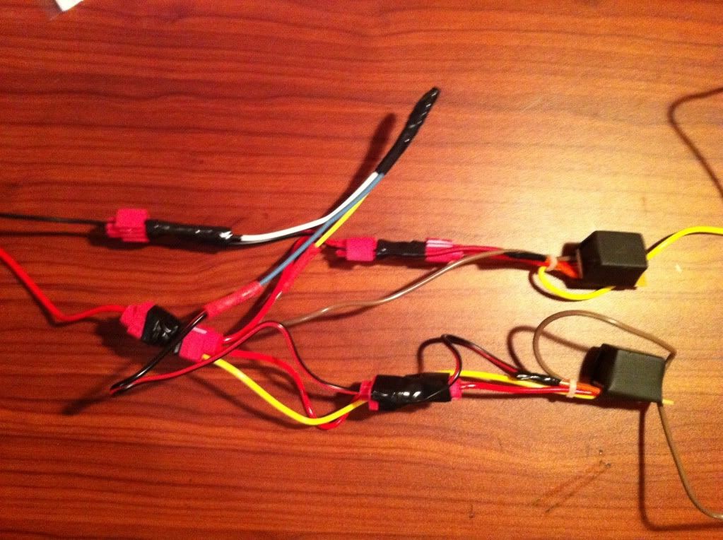
In the end, you'll have 4 exiting wires:
- Yellow from one of the relays -- This goes to the gray wire in the steering column.
- Brown from the other relay -- This goes to the solenoid.
- Red wire -- To Arm switch and ultimately 12V source.
Next, I took the whole thing and wrapped it up in tape. I left one of the mounting holes on the relay open on one end and the 4 wires exit on the other end. This is a pretty good spot to mount it in the car (driver's side fuse panel):
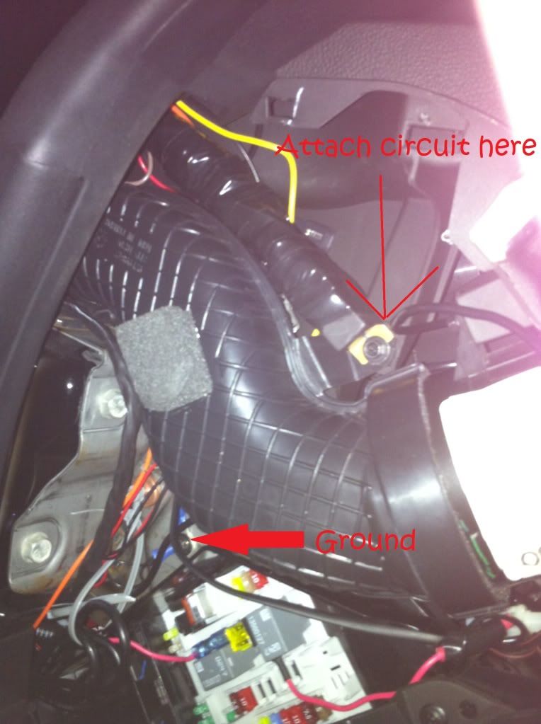
The above pic also shows where you can ground the circuit (put ring terminal on end of black wire and attach to screw as shown)
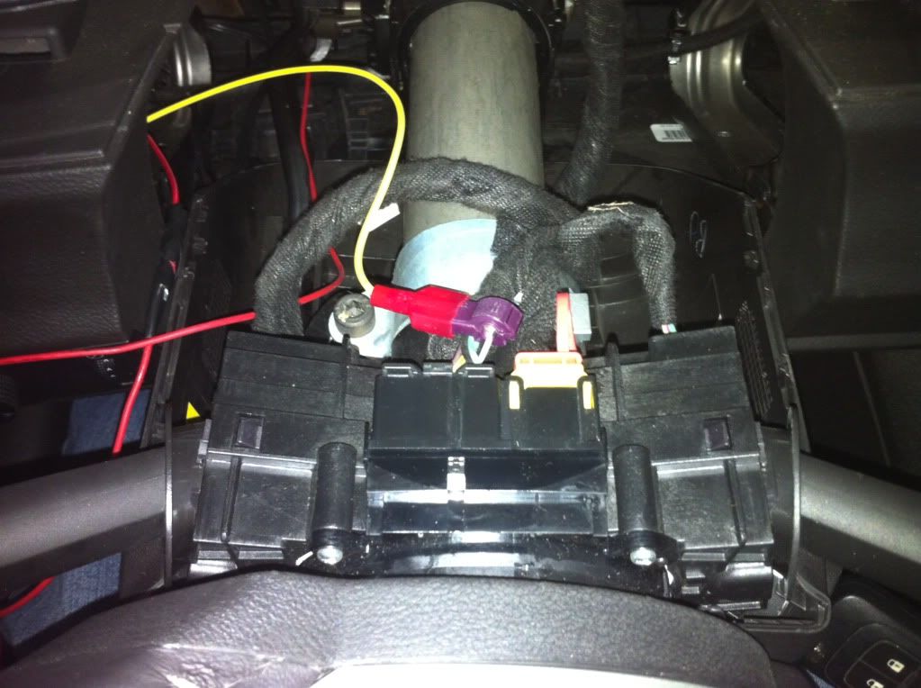
Now, run the yellow wire up to the steering column and tap into the gray wire shown here:
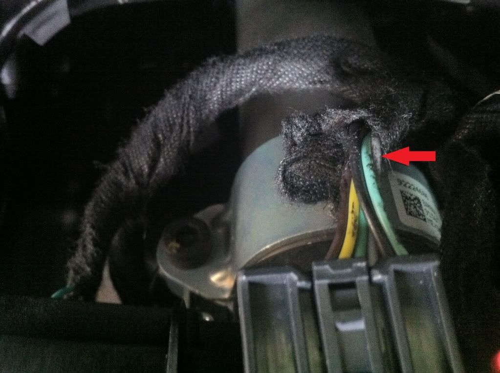
Once you're tapped in, it will look something like this:
The brown wire needs to pass through the firewall and connect to the solenoid. There is a hole in the firewall that is perfect for this.. For the location, see
this thread.
Now, is where things become dependent on where you locate the switch..
All's left to do is run the red wire to the switch and then to 12V..
A good place to tap into 12V is the BCM (it's above the accelerator pedal). There are 3 red/white wires that go into the white plug (farthest plug from front of the car). Run red wire here... Don't forget to add the fuse!
Will add pic..
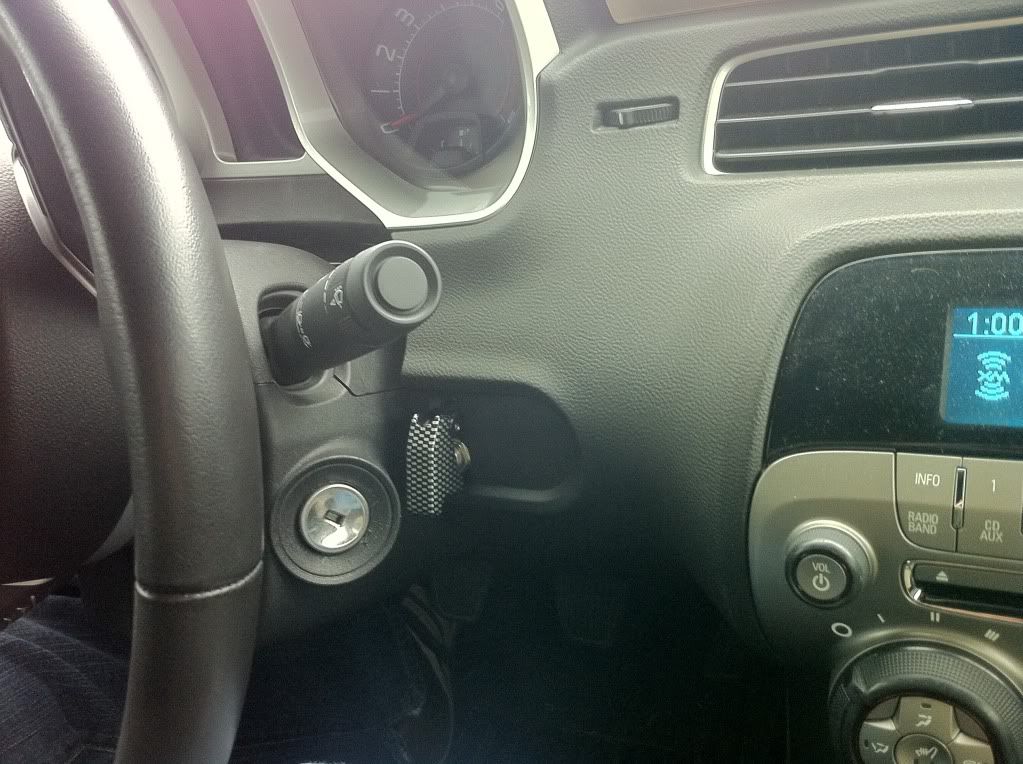
This is where I put my switch... If you have a HUD, you'll obviously need to find another spot..
I'll finish this up when I get some more time...
