READ ORIGINAL ARTICLE HERE
PART TWO:
Cylinder Heads
One of GM Powertrain's strong points is its ability to engineer really great cylinder heads and, the LS7 is clearly demonstrative of that ability. A forged crank, Ti rods, lightweight pistons and dry sump oiling are neat stuff in any production car, much less one of the Vette's price range, but, from a performance standpoint; the most significant pieces of hardware on an LS7 are its cylinder heads.
Although C6 debuted in 2005 with the LS2, Gen 4 Small-Block V8 under the hood, the LS2 head was a actually a Gen 3 hand-me-down, having been used on the 2001-04 LS6. The LS7's head was the first Gen 4 head to go to production and if there had been a mission statement for its development, it might have been: "maximum performance with minimum complexity".
In late-Summer, 2003, the Society of Automotive Engineers magazine Automotive Engineering International published an article about a head with three valves-per-cylinder being part of a 500-hp, Corvette engine. Math art in the AE article and photos which appeared on the Internet later showed complex pushrod valve gear. This article sparked speculative chatter on Internet forum sites along with articles in other magazines suggesting that a 24-valve engine would be in the "next" Z06.

The most important part on the engine is this cylinder head. Ti intake, raised ports, rolled-over 3° and fully CNC'ed. It's the key to the LS7's amazing performance. Image: Mark Kelly/GM Powertrain.
While the the "3-valve" had been under development by GM's Advanced Powertrain Group and might even have been a last-ditch attempt at getting 500-hp out of a 6.4, it was never a part of the LS7 program. The team at Powertrain working on the seven-liter stuck with the two-valve configuration which had worked so well with the LS1, -2 and -6 engines. In a discussion of the three-valve head, Jordan Lee, who's now Chief Engineer for Small-Block V8 Engines, told the CAC, "Our philosophy is not to add technology for technology's sake. If technology is really not a performance benefit, we won't implement it." As such, the three-valve head became part of the LS7 mystique and another curious footnote in Corvette engine history.

A prototype Gen 4 V8 with the three-valve head circa Summer 2003. Image: Dave Emanuel.
Using computer analysis tools, port models in "flow boxes" and single cylinder test engines, the cylinder head team, under Design Responsible Engineer, Dennis Gerdeman, developed and tested a multitude of intake port, exhaust port and combustion chamber shapes before ordering any prototype LS7 parts. This process added two more big architectural changes to the square ports and revised pushrod locations developed for the six-four head. First, valve angle was decreased from 15° to 12°. Secondly, intake port was raised. Its floor was lifted 9-mm. (.354-in.) and its roof was raised 5-mm (.197-in.), for an overall cylinder head height increase of 7-mm (.284-in.). These changes improved air flow. Also, at this point in the development, combustion chamber displacement was set at 70-cc's. For this article, the CAC recorded a long interview with Dennis Gerdeman. It began with a discussion of the early LS7 head work.
"We were working on this (6.4L LS6 successor) and they gave us a target (450-hp) and we achieved it early in development," Gerdeman told us. "It wasn't long after that when (GM upper management) came back and said, 'We need to raise the bar and increase our target to 500 horsepower.' It was really late in the development stage and that sent us all scrambling. That's when we started pulling out all the stopsthe bigger bores, the titanium rods and inlet valvesand really stretched the limits of the Small-Block.
"It was (early) 2004 when we were going through this accelerated development crunch. A lot of it was hardware. When we were looking strictly at air flow, we were doing a lot of work on the air flow bench, nearly all of it with single cylinder flow models. From an air flow analysis standpoint, we were very limited back then. We weren't nearly as developed in CFD (Computational Fluid Dynamics) analysis tools as we are, today."
The head is cast of 356-T6 aluminum by Nemak using the semi-permanent mold process and cold-box cores. For machining, the head is shipped to the same Linamar facility which does the block. An LS7 head is machined entirely by five-axis, Computer Numerical Controlled (CNC) machining centers having automated tool changing. The use of 5-axis CNC allows all machining operations of critical head featuresports, chambers, valve seats and the deckor "joint surface" as cylinder head engineers sayto be accomplished with no set-up change between them and that enhances the accuracy of the machine work. We asked Dennis about the decision to use all CNC machining for the LS7 head.

Top is the LS3 descendant of the 6.4 head and bottom is the LS7 head. They were photographed from slightly different angles so, due to an illusion, the LS7 port size doesn't seem as large as the 6.4's but it is. The key features of these two images are the difference in valve angles along with: 1) the contour of the short turn radius of each head and how the LS7's more developed short turn improves air flow and 2) the height of the LS7's port floor and how the port entry is raised up above that of the six-four. Image: Author.
"The Engine Power Analysis Group told us, 'You're gonna need such-and-such air flow to have a chance at 500 hp.' We had a good feel for the geometry we needed for the perfect transition from the ports, across the valve seat and into the chamber. We also needed to reduce cylinder-to-cylinder (air flow) variation and you just cannot get there with a conventional casting and machining process.
"With conventional castingsand we have some excellent casting supplierstheir variation is too high to ensure those perfect transitions. With conventional plunge machining of the valve seat and casting draft (note: "draft" is the slight taper, perpendicular to parting lines, required with sand-cored features of semi-permanent mold castings, such as ports. This "core draft" is required in order to extract the sand port cores from the steel tooling in which they are created.), you can't get those perfect transitions. That's when we decided to CNC. At first it was the chambers and the valve seats but then, looking at the ports, we said, 'There's no way to get the airflow we need without CNC machining there, too.' The only way to get that is to do an unconstrained, three-dimensional, CNC'ed port shape.
"We have the seats and guides installed. They CNC the ports, chambers and seats in the same machine set-up. There's no stack-up from fixture-to-fixturelittle or no variation from the CNC porting, to the seat machining and to the joint surface, so our chamber volumes and our seat machining transitions are as good as you can get. It all comes down to the repeatability of CNC machining. Any variation from that is very, very small."
Other subjects Dennis and I covered were how Katech's C5-R engine program influenced the LS7 cylinder head development and valve unshrouding. Finally, we got into Mike Chapman's work.
When a valve opens, there are parts of the valve opening which are closer to the combustion chamber or cylinder bore walls than the rest. The closeness of these walls is called "shrouding" and it restricts air flow though the valve opening. Obviously, the more you move the valve opening away from the chamber or bore wallsi.e.: "unshrouding" the valvethe less restriction there is and the better your air flow will be.
"We went to the C5-R guys at Katech and looked at their valve geometry, sizes, positions relative to the bore walls and we decided that was a great place to start," Gerdeman continued. "We took the six-four head and kinda melded it into stuff that we gleaned from the C5-R. We still had to start with the six-four head because there were certain manufacturing limitations far as geometry and production durability. The C5-R. started us down the path of siamese valve seat inserts, which was a real unique feature for ussomething we'd never done before. The siamesed seats were driven by the valve size and getting maximum unshrouding from the bore wall. We were making a lot of prototype flow boxes that we could measure on a flow bench and playing with different configurations but, until we went siamesed (and unshrouded the valves); we just weren't getting the air flow we needed.

A key development in the early stages of the LS7 head program was going to siamesed valve seats. That unshrouded the intake valve thereby improving airflow. Image: Author.
"We had transfer machining lines at the time. On a transfer line, trying to change things like valve angles and locations is impossible without huge investment. We decided, with this volume, to go with an outside machining company. After sourcing, it turned out to be McLaren which ended up (Sept. 2003) getting bought by Linamar.
"McLaren had worked with Chapman Racing. They said, 'Hey, talk to Mike (Chapman) and let him take a stab at this thing.' We had already developed a siamesed layout and what we thought we wanted for unshrouding and valve sizes. Chapman started working through the intricacies around the valve seat, the angles, the blends to the port and the port's geometry around the valve guide. He did a lot of tweaking of port shapes. At the time, we were pretty happy with our intake flowChapman did a couple little tweaks therebut he spent a lot of time on the exhaust valve seat and port."
Next we got into a long discussion about various design features of the LS7 which contribute to its performance. The first subject Dennis covered was the all-important short turn radius which, for those who are learning cylinder head nomenclature, is where the port floor curves down, then transitions to the valve seat.

The short and long turn radii along with those transitional areas of which Dennis Gerdeman spoke during our interview are easier to understand when you have a saw-cut head to look at. Image: Author.
"From an inlet standpoint, it's the height (of the port), the shape of the short turn and the area schedulehow the (cross-sectional) area changes as you go down the length of the portthat's important. We spent a lot of time developing the short turn and from a CAD standpoint, it was a lot of complex geometry because, whatever we ended up with; we had to have a CAD model.
"Another focus was the shape of the seat insert after CNC machining and its transition across the 45° valve seat and into the chamber. Making those transitions as smooth as possible and as much like a radius as it comes out of the port and into the chamber is another key feature. You want those geometries as close to a radius as possible, but you still need a very defined flat for the valve seat, itself. There are four angles plus a radius. It is very subtle as the fourth angle blends into the radius. This radius is different on the short turn side than it is on the long turn side. The short turn, the long turn and even the sides: they're all a little differentanother advantage of CNC machining. If it's a cast port or an as-cast seat insert, you are driven to the same geometry all the way around.
"The exhaust side is very similar," Gerdeman continued. "Again, there's a unique area schedule. We spent a lot of time on the exhaust fine tuning that. Also, the exhaust has even more of a pronounced difference between the short turn and the long turn sides.

The exhaust portthe parts of the chamber just below it have the same type of turn radii and transition areas. You can see why LS7s exhaust ports flow really well. Image: Author.
"Area past the guide is critical, but we still had to keep as-cast material around the valve guide for temperature control to avoid durability issues. In some (racing) cylinder heads, almost all the as-cast aluminum is goneracers will feather the aluminum material out almost to a knife-edge adjacent to the guide. We've got to still meet our durability targets, so we can't machine it all away. The valve guides are installed in the head prior to the CNC machining. We have an as-cast port shape which provides roughly 1.5-millimeters of finish stock (left for the CNC work) everywhere. When they do the CNC machining, they have to come up and clear that valve guide insert. The CNC program can only get so close, so you're going to see as-cast material (at the end of the guides) just because of that.
"It's really designing the entire chamber as a complete system. It's the maximum unshrouding on the sides where the valves come closest to the bore wall. The key is developing blends and transitions so the airflow across the valve seat stays attached to the shape of the chamber and ports as much as possible. In the case of the inlet, air flow comes across a very open area towards the exhaust side and you want it to stay attached to that wall. Any time you start getting detachment of the air flow, whether it's the ports or the chamber, you get turbulence which drives your effective area down and you start losing air flow. It's like you're making the port or the chamber smaller.
"The four angles on the intake seat really help, even with high lift flow. The more angles you can cut, the more of a perfect radius you end up with. At low lift, a lot of flow on the inlet side is going to come from the unshrouding of the valve and how far it is from the bore. Then, at the higher lifts, it's how well you can keep that air flow attached to the walls and reduce turbulence.
"We worked the backside of the intake valve and the geometry transitions across the seat angles to valve stem. We, also, tried various valve margin heights and settled on what we have there as best for air flow."
Near the end of the LS7 cylinder head development, Gerdeman and his team looked beyond just air flow. They studied how the air and fuel mixed in the chamber as it flowed across the valve seat and as it continued to mix once the intake valve closed and the compression stroke began. They, also, looked at the homogeneity of the mix near the spark plug and, once the ignition kernel developed, how the flame front propagated across the combustion chamber.

This is a view from the port entry, down the intake port towards the valve guide. Note how the guide is streamlined but not knife-edged or removed all together like is done with some racing heads. Image: Author.
http://www.camarohomepage.com/ls7/images/784.55.jpg
Same type of view down the exhaust port. Image: Author.
Some of this research was done at Chapman Racing with a "wet flow bench" which mixes colored liquid with air flow inside a transparent bore to simulate a mix of fuel and air flowing into the cylinder. The see-through bore and the color allowed the cylinder head engineers to observe the homogeneity of the air-fuel mix as it came past the intake valve seat and flowed across the chamber then into the bore as the piston moved down in the cylinder. The LS7's cylinder volume was huge and getting a homogenous a mix as possible was a challenge but an absolute necessity if the engine was going to meet fuel economy and exhaust emissions targets.
The engineers' observations at Chapman racing encouraged them to experiment with a aerodynamic device in the roof of the intake port between the valve guide and the long turn radius. Described by Dennis Gerdeman as a "wing," it looks more like a ridge or a deflector. It is intended to impart a specific directional swirl to the flow as it enters the cylinder bore while the piston moves down on the intake stroke.
The motion imparted by this deflector is complex. It's somewhat like swirl, towards the spark plug, but it, also, generates downward spiraling motion towards the centerline of the bore. In the end, this one feature of the LS7 intake port did much to enhance the homogeneity of the air-fuel mix in the engine's large cylinder volume and contributed to the engine's high combustion efficiency.

The deflector which was added to the intake port just above the valve after research on Chapman Racing's web flow bench. What's to bet half the head porters who've tried doing LS7 heads, grind that away? Image Author.
Interestingly, while Chapman's wet flow bench was cutting edge stuff in 2004, it's an anachronism, today. By the late '00s, GM's analysis capabilities had grown tenfold such that CFD, with an enhancement called "rain drop analysis," could simulate wet flow down ports, though valves and seats and into cylinders and do it in a few hours of computer time rather than weeks of work with flow boxes on a wet flow bench.
Judy Jin, Design Release Engineer for the LS7 cylinder head, tells us that two different valve seats are used. The intake seat is made of a specific material, PMF 28, which is compatible with the titanium intake valve. The seat couldn't be too hard because, once you wear through the titanium valve's hard-faced coating and into the softer, but very abrasive titanium below, both parts fail in short order. You have to protect that coating, but still have a seat that's hard enough to avoid valve seat recession. Since they had never done titanium intakes before, the cylinder head team consulted with Federal-Mogul, seat insert supplier for other aluminum Gen 3/4 heads, and leveraged F-M's experience with titanium valves for racing. Actually, the first material F-M recommended and GM tested, PMF 28, turned out to be the one which worked.

A copper-infiltrated LS7 exhaust valve seat prior to installation in the head. Image: Author.
The exhaust valve seat, also supplied by F-M, is Brico 3220 material, used in a variety of GM aluminum heads. The Small-Block does not have coolant flowing completely around the valve seat inserts. Because of the siamesed valve seats, there's no cooling at all in the "valve bridge" between the ports. When things get extra hot, you want rapid transfer of heat away from the valves and seats and into the water jacket. For that reason, the exhausts use "copper-infiltrated" seat inserts. Federal-Mogul, takes a powdered metal blank and puts a copper cap over it. They run it though an oven, the copper melts and wicks into the microscopic voids in the powdered metal. The copper-infiltrated seats improve heat transfer out of the valves, through the seats and into the water jacket by 4-6%.
Ms. Jin added that, because the valve centerlines are so close, the valve seat installation at Linamar is a multi-step process, most of which is done in the five-axis CNC set-up which also machines all other critical features of the head. First, a separate CNC cuts a small "scallop" into each intake seat insert. Next, during the head's main CNC session, the seat pockets are cut such that they overlap slightly, creating the siamesed appearance. The round exhaust seats are installed into the head's exhaust seat pockets and, finally, each intake seat insert is installed with its scallop fitting over the side of the adjacent, exhaust seat insert. This process eliminates any bi-metal machining of the pockets which would occur if the exhaust insert was installed into the head, first. This is the preferred process because the seat pocket tooling produces the highest quality results if it cuts only aluminum.

Judy Jin, a Small-Block cylinder head engineer, led the discussion about LS7 valve seats and valve seat and face angles. The finishing of the valve faces and seatsfour angles on the seats and two or three on the facesis more sophisticated than most production engines and more typical of a racing head. Image: Author.

This image details the space near the intake valve seat. The LS7 intake seat and transition areas are a very sophisticated system intended for one goal: maximum air flow. Image: Author.

The surfaces in the vicinity of the exhaust valve seat are designed with optimal exhaust gas flow in mind. Image: Author.
After the seats are installed, they are machined to the proper angles. On the all-important intake, starting at the combustion chamber roof, the seat angles are: 39°, 45°, 60° and 71.83° followed by a radius. The exhaust seats are cut with 38.17°, 45° and 76° angles, then a radius. In both cases, the valve face seats on the 45° portion. Each seat and radius are machined by one milling tool in a single plunge movement of the 5-axis CNC's table.
The internal structure and the cooling jackets of the LS7 head are much the same as that of other Gen 3/4 heads going back to the LS1. "Nothing special in the cooling jackets compared to other Gen 3/4s. You try to get the coolant as close as you can everywhere else on the back side of the chamber, "Dennis Gerdeman told us, "but you still have to have very large fillets to handle the high combustion pressures. It's structural integrity vs. cooling, so you have to strike a balance between the two. Nothing different though than the other Gen heads. They all have that same balance."
Even seemingly minor features can be of utmost importance, such as the small horizontal pad in each combustion chamber next to the spark plug. "Those are 'locators,'" Dennis told us. "When the casting is first set-up for the initial machining operation, they need locators. Each chamber has one because you want them all to be common (have the same displacement), but we use the pads in two end chambers and a horizontal pad on the intake side of the deck face as the initial locating points for the machining operations. We don't machine them away because, if we ever have an issue identified later on and believe it's a casting issue, we want to be able to go back to the cast locators and take CMM (coordinate measuring machine) measurements."
Linamar also assembled the heads then shipped them to the PBC in Wixom. When you see one of these heads before it goes on an engine, you'll marvel at its appearance and feel. Its huge, glittering, CNC'ed ports, gleaming titanium intake and stainless steel exhaust valves and the shimmering, silvery combustion chamber walls are sweet eye candy for we engine guys. "The appearance of the CNC work is a balance between cycle time and surface finish," Dennis Gerdeman commented. "Ideally, you'd want to make it smoother but when it really came down to it, the gains were marginal at best. The cycle time already is so long. When you consider you have to do eight ports and four chambers and all the seat machining, it's a lot of time in the machine. Each head takes about two hours."

Left to right: the Author, Performance Build Center Engine Assembler, Mike Priest and GM Powertrain Communications Manager, Tom Read. We all agree. Each of us should have one of these heads on display in our living rooms because they are so pretty. Image: Mark Kelly/GM Powertrain.
Even the exterior surfaces of the heads have a "premium" look and feel because of the semi-permanent mold process used to cast them. Like the crankshaft, the LS7 head is one of those parts that's just too damn pretty to be run on an engine. All and all, it's a high-tech piece both in performance and appearance. An interesting bottom line on the LS7 head comes when one compares it's airflow numbers with those of the head on the Camaro SS's LS3. In a straight-across comparison, the LS7 head flows about 20% more air, a huge improvement.
We asked Dennis Gerdeman, if he could revisit the LS7 head design, today, what he'd do differently. "From an analysis standpoint, our tools have improved significantly over what we had back when we developed this cylinder head," Gerdeman replied. "I would probably play with valve sizes, again, and locations within the chamber just to see if there's a little more we could squeak out of this from an airflow perspective. I don't think it would change significantly, but we may have ended up with a little larger exhaustmaybe a slightly smaller intake. It may even have led to a slightly different intake port shape with a different area schedule.
"Those are probably the two things I'd like to revisit: the intake port and small tweaks to the valve sizes or centers, because with the tools we have today, you can accomplish that in hours instead of weeks. Before you had to make a CAD model, send it to a job shop and have them cut you a flow box then, flow it on the bench and try again. Now we can do it with analysis in a fraction of the time."

The LS7 head gasket is standard faire for today's high-performance engines, a 3-layer, multilevel-steel (MLS) design. Image: Mark Kelly/GM Powertrain.
Dennis and I ended our LS7 cylinder head discussion talking about how the engine's mystique comes from the power it makes without boost and its drivability. "When you think what you can pull out of a Small-Block naturally-aspiratedmaking that 500-hpit's pretty amazing," was his final observation.
Cam and Valve Gear
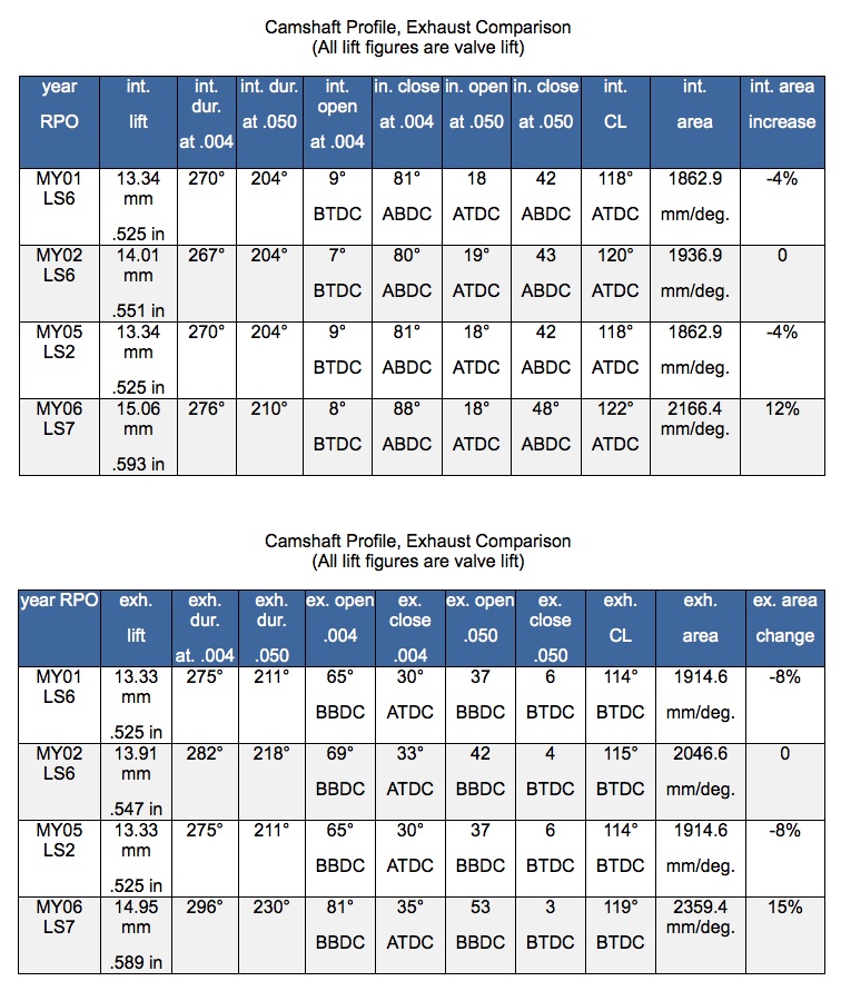
LS7's valve train was yet another field on which GM Powertrain moved the technology ball forward for another first down. Not only does the LS7 have a hydraulic lifter valve train which runs to 7100 RPM, 500-RPM higher than that of the C5 Z06 engine and beyond the capability of even the solid lifter engines of the bygone Musclecar Era, but it has a huge, 2.20-in intake valvethe largest ever in a production GM V8, besting the 2.19 intake used in Camaro high-performance 396 and 427 Big-Blocks of late-'60s. Valve lifts are an astonishing .593-in. and .589-in. for intake and exhaust, a significant leap past the '02-'04 LS6 camshaft, previously GM's most aggressive. Duration at .050-in. lift jumped 6° to 210° on the intakes and a whopping 20° to 230° on the exhausts. While lift and duration are often cited in comparisons of cams, a more telling measurement is lift area which, when you graph the valve lift, is the area below the curve. With the LS7 cam, compared to LS6, lift area rose 12% on the intakes and 15% on the exhaust, both significant increases.

Like all roller cams, the LS7 unit is machined from a steel billet. The lifters come in fours in plastic lifter guides. Image: Author.
"The design philosophy on that cam is similar to the LS6, the ramp designs are very aggressive," Jim Hicks, who lead the LS7's valvetrain development. "We were limited in what we could do with camshaft because you've got a cam bearing diameter and the nose can only go so high. We had to drop the base circle down to a smaller radius so the nose radius could be larger. In addition to that, we went to the higher rocker ratio and that gets us to the (valve) lift we needed. Then, we tried to make everything as light and as stiff as possible.
The higher rev limit, a gargantuan intake valve, more aggressive valve train velocities and a big increase in lift area required some trick valvetrain features previously reserved for racing applications. The first task was to reduce valvetrain mass. Inspired by Katech's C5-R 427s using a titanium intake valve, Hicks and the LS7 valvetrain engineers decided on a Ti intake and a hollow-stem exhaust valve as two ways to get the mass down. Despite a valve head which is 22% larger, the ti intake weighs 19-grams lessa 21% reductionthan the smaller diameter and shorter stemmed, LS2 intake valve. The ti intake valve, supplied by long-time titanium valve manufacturer, Del West Engineering, was the World's first application of the super-light metal in a production automotive valvetrain.

Back in the day, people thought any high-RPM application needed a dual-row, timing chain, but in recent years, GM has developed some pretty stout single row, true rolling chains. Evidence of that is the LS7's timing set. Still not convinced? The Katech chain set, as used in the C5-R 427s, is, also, single row. Image: Author.

This is what a PBC assembler sees during LS7 assemblya view only an engine wonk can love, if you ask us. You can't miss the humongous Del West titanium intake valve. A small chamber, siamesed seats and minimum valve shrouding means the valves almost touch each other. The curves of the chamber walls and roof along with the CNC machining is sweet eye candy, too. Image: Author.
"We started with a hollow-stem, steel valve, kinda like the LS6, with a very thin head, "Hicks said. "We reached a point where the power the engine was making was flexing the valve head enough that we had problems with the valve heads cracking. Combustion pressure causes the valve head to flex. Imagine pushing on the top of a tin can, moving it in-and-out. If the section (thickness of the valve head) gets too thin relative to the amount of pressure in the chamber, you'll get this flexing and, eventually, a pie-shaped section breaks off. We found this with test engines. At the time, we were, also, doing some work with Katech. They were using a lot of our parts in the World Challenge, the first year of the Cadillac CTS-V program and they failed some of our valves, as well.
"We had to make a change and going to a thicker-head steel valve wasn't an option," Hicks continued, "because we wanted a 7000 RPM red line. We looked at a couple of alternativessome really kind of radical. ultra-light steel valves. I tested a few of those and they failed miserably. Then we said, 'Alright. We gotta do what ever it takes.' We went to the titanium for mass and strength because, with the titanium head you could go to a flat, almost no cup on the combustion facemake a nice, thick section through thereand not take a big mass penalty, so you end up with a lighter valve which is also strong. (The LS7 intake) was the first production application for Del West and the largest diameter titanium valve in any production engine."

Jim Hicks, who was the lead engineer for the LS7 valvetrain explained that the cam's base circle was made smaller so the effective lobe lift would increase. That along with 1.8:1 rockers resulted in the amazing (for a production cam) valve lift. Image: Author.
The same protective, CrN coating used on the connecting rods is on the intake valves but getting that coating just right was a tough task for Jim Hicks and the engineers working on the LS7 valvetrain. One of the issues they had to address was a "Ti dust wear" problem, similar in nature to what afflicted the connecting rod development. When the CrN coating wasn't right, it would fail and highly-abrasive Ti dust would develop between the valve stem and guide causing rapid guide wear. "Developing the stem coating which was going to work well with our production-style, PM guides was another challenge. Most racers use bronze guides or some other type of aftermarket guide which is cost-prohibitive. A moly-sprayed stem, which is typically used a lot on titanium valves (for racing), is very expensive. We wanted to come up with an alternative, so we worked on a chrome-nitride, vapor deposition coating. It took a little development, but it worked out really well for us. It was more cost-effective and just as good or better than the moly spray. There's some tricks to that process and we worked with Del West in developing them. The parts need to be very, very clean. The right processing steps need to be used. The coating thickness is very important and needs to be maintained to a tight tolerance. I think Del West is using it now for some of their aftermarket parts, too."

Racy stufftitanium intake and hollow stem exhaust valve. The stems are gun drilled, filled with sodium, the SilChrome head is welded in place, then the valve is machined. Image: GM Powertrain.
The intake valve faces are machined at 45°, 30° and 10° and this is done before the CrN coating is applied because the coating also enhances face durability of titanium valves. Typical of Ti valves, tool steel "lash caps" are used on the ends of the valve stem. "We actually tried to get away without a lash cap," Jim Hicks said, "and do a welded on, steel 'wafer' which was another development program. We were trying to friction weld it. You can do it, but it's not consistent enough and you can have some which come apart. That program was unsuccessful, so we ended up just using a conventional lash cap like they use on racing engines."
The LS7 uses unique valve springs. They are the typical GM "beehive" design, but they are 0.160-in. taller than all the Gen 3/4 springs GM used previously. The extra height is to accommodate the LS7's greater valve lift. These springs have 16-lbs. more open pressure, too.

Face angles on both valves. On the both there is no specific top cut, rather the part of the finish machining adjacent to the 45° face is done at 10° on the intake and 25° on the exhaust. Image: Author.
The exhaust valves have 2143 stainless steel heads for heat resistance and hollow, sodium-filled, SilChrome stems which are induction-hardened to have a good wear surface for the rocker arms. The benefit of a sodium-filled, hollow stem is mass reductionabout 18%and, because sodium is an excellent heat transfer fluid, getting heat out of the valve head and into the guide. Exhaust face angles are 45° and 25°. Both valves move in powdered metal guides.

Lash caps go over the tip of the stem of a titanium valve and prevent direct contact between the rocker arm and the stem. Without a lash cap, the stem of the Ti valve and the rocker arm tip would quickly wear. "Beehive" springs have been used on Gen 3/4/5 engines since the Camaro LS1 was introduced in 1998, however, the LS7 uses a specific beehive spring with more height and higher open pressure. Image: GM Powertrain.

LS7 pushrods are longer and have a ticker wall than do other Small-Block units. From a performance standpoint, the weight of the pushrod is not as important as it's stiffness. Image: Mark Kelly/GM Powertrain.
To get to the 7100-RPM red line such that the Z06 could go 0 to 60 in first gear required more than just "light-weighting" the valvetrain on the valve side of the rocker. It had to be as stiff as possible on the pushrod side. The pushrods are steel but, compared to other Small-Block pushrods, are larger in diameter, have more wall thickness, and to accommodate the taller head, greater length. Obviously, all that makes for a heavier pushrod, but, from a performance perspective, there is a greater benefit in keeping the pushrod side as stiff as possible, as opposed to as light as possible.

A pair of LS7 rockers showing the offsets of the intake part. Image: Author.
The LS7 rocker arms are made of investment-cast steel, the same material as other Gen 3/4 rockers. The investment casting process is ideal for production roller rockers because it's strong, allows complex shapes with mass only where its needed and is cost-effective. The intake rockers are a unique design with the pushrod seat offset 3-mm to the left and the valve stem pallet offset 6-mm to the right, allowing the pushrod to be moved over to make room for the revised intake port location and shape. Typically, Gen 3/4 Small-Block rocker arm ratios are 1.7:1, however, the LS7 was the first to use a 1.8:1 rocker ratio. The reason for that extra "tenth-of-a-ratio is the same reason hot-rodders put 1.6 rockers on traditional Small-Blocks: more valve lift!
Lastly, the LS7s valve lifters not only play an important part in the valvetrain's 7100 RPM capability but they are a stalwart design, as well. Other than some occasional small changes in oil metering rates and plunger travel, the part used in a 2013 LS7 is virtually the same part used in 1987, when GM introduced roller hydraulic lifter cams to its engines with the LB9 305 in the old 3rd Gen cars. The same basic part, in service for 26 years speaks volumes about the soundness of the design

The LS7 hydraulic lifter is durable at 7000 RPM. Amazingly, it's a 26-year old design. It was introduced on the LB9 of 1987 and other than some changes in hydraulics and plunger travel, it's still used today. The trick, Chevy Performance lifter is the same except it uses a lightweight ceramic check ball rather than a steel ball as do OE lifters. Put those in an LS7 with an aftermarket cam and, given the right valve spring pressure, the engine can rev even higher. Image: Mark Kelly/GM Powertrain.
Induction and Computers
The LS7's intake manifold shares some qualities of previous Gen 3/4 intakes. It's made of black Nylon 6, no coolant flows in it and the throttle body and injectors bolt to it. Other than that, it was a new design. "We had to match to a different port in the cylinder head," John Rydzewski told us. "We tried to get as much flow as possible. The intake runners are sized and tuned for the engine's performance envelope. They're a little bit shorter (than those of LS1, 2 and 6). It's a three-piece, molded and vibration-welded assembly with a seal to prevent crosstalk between runners. It uses a 90-mm throttle body, the biggest we make at GM."

The LS7 intake is a bit different than that used previously. Obvious is its rectangular rather than round ports. Maybe not so obvious is a bit less runner length to better suit the LS7's torque curve. Image: Author.
The intake manifold, throttle body, fuel injectors and fuel rail are assembled by a supplier and shipped to the Performance Build Center in Wixom as one piece. The LS7 uses a "4-bar" fuel system which runs at 400-Kpa or 58-psi. The injectors flow 5-gram/second (39.6 lbs/hr.) at 58-psi. They're made by Bosch have all stainless internalsthe norm because of ethanol-blended gasolinesand are a ball-and-socket-with-dispersion-plate design.
The LS7 debuted in 2006 with the GM E38 engine controller which uses a Freescale Power PC chip as its main microprocessor. Interestingly, the Power PC "Reduced Instruction Set Computer " (RISC) chip was originally developed in 1991 by an alliance of Apple, IBM and Motorola (now Freescale) for Macintosh personal computers. Today, Freescale PPC chips are common in all kinds of automotive engine control, chassis control, body control and telematics applications.

The LS7 throttle bore is 90-mm, biggest in GM. Even the LSA's throttle body has only an 87-mm. bore. Image: Author.
There are four slightly different versions of the LS7's E38. The first was used in '06 and '07, the second in '08, the third in '09 and '10 and the final variation for '11-'14. All these different versions increased processor speed, enhanced memory maps and eventually added a second micro processor.

A Z/28s E38 engine controller. Image: Author.
The Final Push
As the LS7 development closed on deadlines forced by GM's intent to debut the engine in the 2006 Z06, the engine's power output had plateaued somewhat below the 500-hp goal set by that pesky senior management.
For a while it looked like 480 was going to be the number," Corvette Chief, Tadge Juechter recalled in a Spring 2012 interview with the CAC, "but then, they pulled the rabbit out of the hat at the end. This was on the eve of production! I'm talking about the end of '04. We're already ordering material to build our nonsaleable validation vehicles at the plant so, we're holding up the presses at that point, trying to decide'Ok, guys, what is the horsepower?' and remember, it was, also, the first engine in the auto industry certified to (the then-new) SAE standard. That was another level of rigor that we had to go though. The very last part released for production was the Z06 badge which said '505-hp'. In fact, we were thinking we'd have to go to production without any number on there because we didn't know what it was going to be."
In this final six-months the key advance which put the LS7 "over the top" was a late modification to the LS7's cylinder case. As we said in the first part of this article, early in the development program, unlike its predecessor LS6, the LS7 block had no main web windows for bay-to-bay breathing. The CAC's discussions with former LS7 boss (and current Chief Engineer for V6 engines), Dave Muscaro, revealed how his team found about another 10-hp by developing block windows which did not compromise strength. "We were pushing 490-495hp for about the last 6 months of development," Muscaro told us. "The one area we knew still had promise was in our bottom-end breathing. If we could improve bay-to-bay breathing, we could reduce the work required by the bottom side of the pistons to move air around. The Corvette is extremely challenging in this area due to the engine's low position in the car. The ground clearance requirements disallow ample room in the oil pan to aid in lower end breathing which puts additional challenges on finding ways to reduce the (power loss in) lower end pumping work.
"So (while other areas of the LS7 development moved ahead) we continued to look for ways to improve breathing by way of the engine block itself. The LS6 utilized openings in the main bearing webs to help its bottom end breathing but, up to this point, we had not been able to identify similar LS7 engine block changes that could withstand the additional loads put on it by the power levels being achieved. After numerous design iterations run through structural analysis computer modeling, we came up with engine block design revisions (one was the change in hone over-travel radii discussed earlier) that incorporated bay-to-bay breathing portalsknown as hone over-travel windowsthat met all structural durability requirements.

A computer rendering of the window and hone over-travel machining which was a big player in GM's final effort in the ruthless pursuit of power which resulted in 505 horses: Drawing: John Rydzewski/GM Powertrain.
"That final look in this area", Muscaro continued, "gave us a design which met the structural requirements and one which we knew would also improve our lower end breathing and therefore increase the engine's power output. Blocks were ordered to this design revision and we began testing them. In those tests, as predicted, we saw an immediate improvement in our bottom end breathing as demonstrated by the engine's power level increase of 10-15 hp. We proved the revision's durability and made the new block part of our production package."
That last block change and a few other little tweaks saw final development LS7s meet the 500-hp goal senior management set almost two years before. The engine was revealed to media in January 2005 at the Detroit Auto Show. GM had decided the LS7 would be certified using the Society of Automotive Engineers (SAE) then-new Standard J2723 "witness test". The SAE Standard to which the dyno test data is corrected had not changedit was still J1349. What's different is: for a manufacturer to say an engine is "SAE-certified" requires that manufacturer test the engine in an ISO9000/9002-approved dynamometer testing facility and that the testing be witnessed by persons approved by the SAE. On 14 March, 2005, the J2723 testing was done and the engine produced 505 SAE net horsepower at 6300-RPM and 470 SAE net pound/feet torque at 4800-RPM. A little over three weeks later on, 10 April, the LS7 was the first engine to ever have its power output certified to the SAE J2723 standard.
We let Dave Muscaro have the final word on the LS7 development. "Working in GM like we do, we work as a team. We don't 'win individually' nor do we 'lose' individually. Rather, when we create a successful production engine program, like the LS7, the whole team has reason to celebrate. Was I glad to be a part of it? You bet! I worked with many great engineers and I sweat the details on each part of the engine with each of them. I learned from them how to make each of their parts great, and when we put them all together, we had the LS7. From airflow and CNC'd ports to all the lube challenges high g-forces bring, to offset rocker arms and titanium valves/rods, to a very large throttle body and a forged crankwe all sweat many little details. So in the end, I consider myself very fortunate to have worked with all these great engineers who helped create the LS7 engine."
Power For Another Z
Fast forward to summer 2011. As to where the GM marketing and engineering folks got the idea to stick the LS7 in a Camaro and make a killer track car? Chevrolet hasn't offered much about the Z/28's origins and development, perhaps because, when the car was introduced in New York, the final stages of that, along with SAE and government certification testing, were not complete.
We'll guess that, about the time Camaro engineers were in the middle of developing the 1LE package for 2013 SSes, they, also, watched as Ford upped the ante with the 444-hp, light-weight, Mustang BOSS 302 Laguna Seca. There might have even been a few internal emails which could have said something like: "Oh s&%t. We didn't go far enough with 1LE!"

Ford used Monterey Historic Automobile Races in 2011 as the backdrop for its media preview for the BOSS 302LS. Image: Ford NA Communications
Part of the solution, of course, was the Corvette Z06's LS7, which made Ford's supercharged five-liter seem kind of puny. It had 505-hp, weighed less than the supercharged LSA, was the same size as the existing LS3 and, best of all, since the C6 Corvette would cease production in February of 2013, leaving the PBC with some unused capacity, a modest quantity of the engines could be available. All that would be necessary to get the LS7 into a Camaro was a few unique induction and exhaust parts along with calibration, validation and certification. The Camaro structure had already proven capable of supporting 556-lbs/ft. torque, but the LS7 only made 470. Through the ZL1 and 1LE projects, a lot of pretty stout driveline and suspension parts already existed.

The BOSS's engine is this 444-hp, 302 cuin., DOHS, supercharged V8. News Flash: this engine's specific output is 1.47, but the big dog of supercharged pony car engines is Chevy's LSA, with a specific output of 1.53.
Image: Ford NA Communications.
It didn't take a rocket scientist to see a potential match made in heaven. We'll guess that sometime in late-2011 or early-2012, at the Camaro Development Team and at John Rydzewski's Passenger Car Small-Block group over at Powertrain, a project got underway to adapt the LS7 for use in a Camaro lighter than a 1LE. The two big development changes for a Z/28 427 came with the air filter assembly and the exhaust manifolds. Other changes were relocating the dry sump tank from the right rear to the front of the engine and changes to the LS7's accessory drive necessary to make a non-A/C version of the engine available.

Because of the limited space under a Camaro's hood, the LS7 air filter assembly and air duct had to be a unique design. Obviously, the 90° bend adds restriction compared to the C6 Vette design, so the Z/28 uses a conical, oil-cotton air filter element to gain back some of that lost airflow. Image: GM Powertrain.
Because of the limited space under the hood of a Camaro, the original air filter assembly developed for the Z06 wouldn't work so, the Z/28 LS7 got a unique air box. Like that on all Camaros, it's on the driver side, behind the radiator core support and connects to the throttle body by an air duct with a 90° elbow. The mass air flow sensor is between the elbow and the filter mount. To restore some of the airflow lost with the duct, there is an open element, oiled-cotton-gauze air filter typical of aftermarket Camaro air boxes.

The Camaro LS7 exhaust manifolds. Again, limited underhood space forced a somewhat more restrictive design than used on a Corvette so, GM went with a stainless steel, Tri-Y configuration which tucks in close to the engine and exits near the rear of the block, rather than the C6 Z06/ZR1 unit, which is a shorty header with a center exit. Image: GM Powertrain.
The exhaust manifolds are different, too, because of the same underhood packaging constraints. Rather than the Z06's shorty header, the Camaro engine uses a fabricated, stainless steel "Tri-Y" manifold. The four primary pipes are grouped, according to the engine's firing order, into two pipes and then into a collector just above the outlet flange which is located at the rear of the engine. While the Z/28's exhaust manifolds and its exhaust system are somewhat more restrictive than what was used on the Corvette Z06, the performance hit is only about 1%a minor issue. Heck, you might gain that back simply by going to ester-based, synthetic lubricants in the engine, transmission and rear axle.
About a year later, word of this new variation of the LS7 began to leak out, first, with the 2014 Camaro VIN Card surfacing and, then, after New Year's, sparse chatter around Camaro Nation hinting of a secret development project, known as "The HP". That veil of secrecy was lifted at the New York Show with the introduction of the Z/28
Durability
Every engine manufacturer does reliability and durability testing. "Reliability" is the quality of being consistent in performance, i.e.:, not failing. "Durability" is the quality of being able to withstand wear, i.e.: being reliable for a long period of time in service.
John Rydzewski and Jim Hicks touched on the reliability of individual parts such as titanium rods and intake valves during the discussions we had with them. Once the entire engine reaches a near-production form, its durability testing begins. Back in the old dayssay the late-'80ssome of the testing was on the dynamometer, but a lot of it was in cars on test tracks. In recent years, with advances in dynamometer technology and with the application of computer controls, more of the testing is done in dyno cells fitted with equipment which can alter the engine's attitude to simulate various acceleration, corning and braking loads. Even with all this advanced dyno testing ability, GM still track tests engines in cars as a final validation of the engine's performance, reliability and durability.
During the cylinder head discussion, Dennis Gerdeman, talked about durability testing.

Would premium ester-based lubricants gain back the 5-hp loss? Image: Red Line Synthetic Oil Corporation.
"We had a durability schedule that we were running," Gerdeman said. "They call it the 24-hour track schedule. It was kind of our benchmark as we were going through the final validation of the hardware, from the whole-engine perspective. They ran a lot of these 24-hour track schedules, so we got quick overnight results. It was a very strenuous test. They did run the cars on the track, but most of (the durability testing) was on engine dynos. We could validate any corrections we were making to any of the hardware componentsnot necessarily to the cylinder head, but to valve train related pieces and all the other mechanicalspistons, cams and so forth."
Another standard GM Powertrain torture test to which the LS7 was subjected is a 300-hour dyno test at wide-open throttle with the load varied such that the engine goes back and forth between peak torque (4800-RPM) and peak power (6300-RPM) in 125 RPM increments. The LS7 also was brutalized with a "thermal shock test" which runs engine coolant ranging between -40°F (burr) to about 250°F (ouch!) through the engine while it's running.
 Acknowledgments
Many people were interviewed for this article and many others assisted in it's production. Thank you to: At GM: Harlan Charles, Mark Damico, Monte Doran, Dennis Gerdemen, Tom Halka, Don Henley, Jim Hicks, Tom Hill, Judy Jin, Tadge Juechter, Jordan Lee, Yoon Lee, Dr. Jamie Meyer, Dave Muscaro, Bill Nichols, Rob Nichols, John Rydzewski, Mike Priest, Shane Smith, and Sam Winegarten. At Katech: Jason Harding, Fritz Kayl, and Kevin Pranger. At Mahle: Aaron Dick. At Del West, Shannon Decker and Mark Sommer. At MPK Photo: Mark Kelly. At Performance Publishing: Dave Emanuel. At: Maritz: Meg Conroy.
Special thanks to Tom Read, Manager of GM Powertrain Communications.
Also, this just appeared in Vette Magazine:
.