You are browsing camaro5 

|
 01-05-2015, 01:08 AM
|
#127 |
|
'It's an experiment'

Drives: [COTW 2/09/15] '11 GPI LSA SC Z/LE Join Date: May 2014
Location: Dallas TX
Posts: 8,709
|
Thanks -- I was a tech for 15 years before I was hurt on the job -- I actually went to college for automotive and diesel technician (along with computer diagnostics) -- as well as welding and fabricating. Learned real early about the whole 'bolt dropping' when one of our test engines (in class) swallowed a carb bolt someone forgot to tighten down during install -- can still hear the bolt hitting the head on that Ford engine. Never forgot that!
Some of my photos show areas uncovered, but that was just me showing the work -- I always cover up when I'm done or into the next step.... I'm old now so I don't move a fast as I use 'ta ;o). Takes me more time to get things done... -Don Last edited by hammdo; 03-05-2015 at 05:26 PM. |

|

|
|
01-05-2015, 02:08 PM
|
#128 |
|
'It's an experiment'
Drives: [COTW 2/09/15] '11 GPI LSA SC Z/LE Join Date: May 2014
Location: Dallas TX
Posts: 8,709
|
OK, was able to clean and install the Passenger's side valve cover -- torqued to 106 inch lbs (did this during lunch break):
 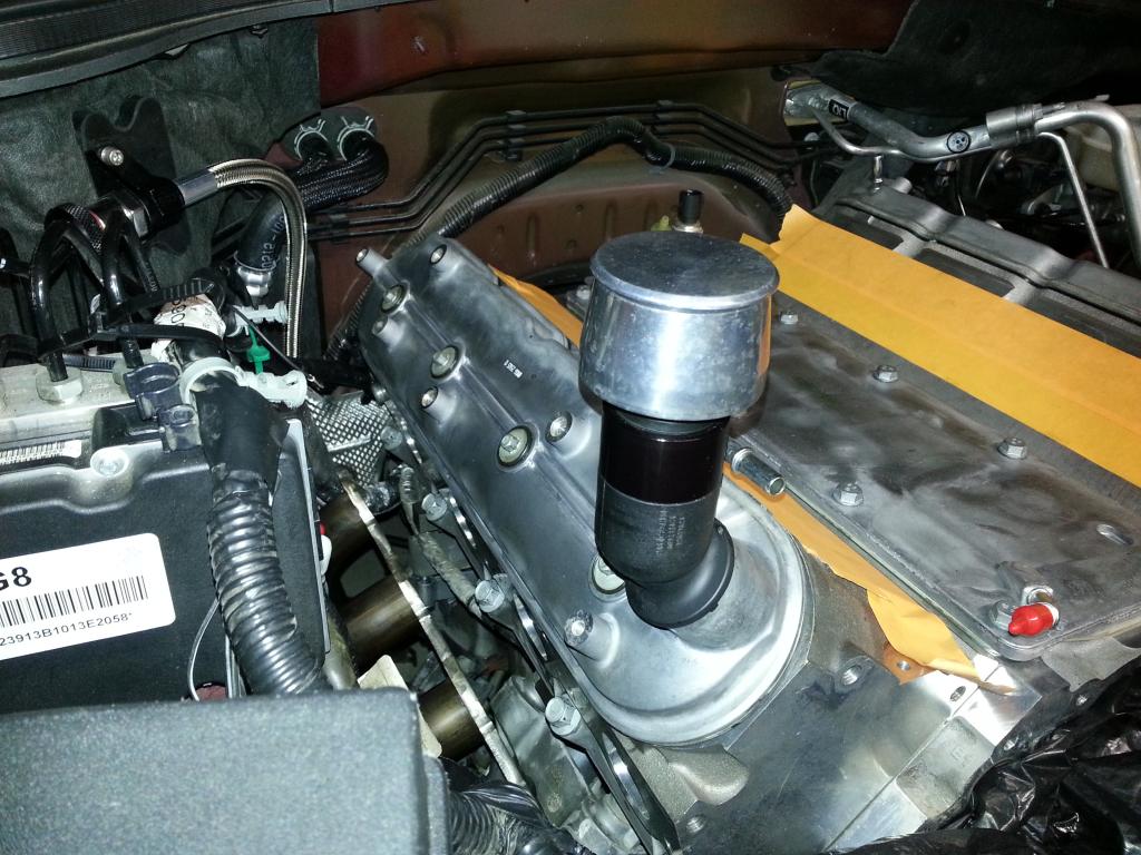 Plugged the openings in the valve covers - to be safe: 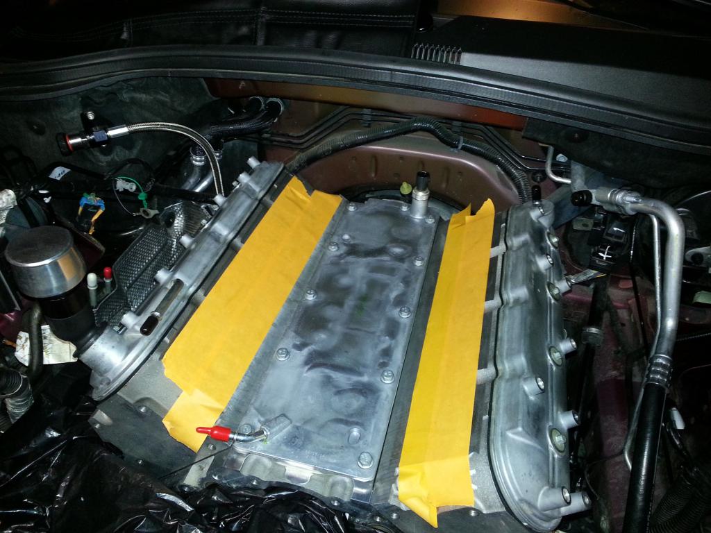 Timing cover is next with new gasket, seal and alignment! -Don Last edited by hammdo; 07-02-2017 at 03:31 PM. |
|
|
|
|
01-05-2015, 07:42 PM
|
#129 |
|
'It's an experiment'
Drives: [COTW 2/09/15] '11 GPI LSA SC Z/LE Join Date: May 2014
Location: Dallas TX
Posts: 8,709
|
OK, time to get the front of the engine back together. First, install the timing chain cover with new gasket. Oiled up the chain and gear first...
Here is the gasket -- it only goes on 1 way:  Cover cleaned and prepped: 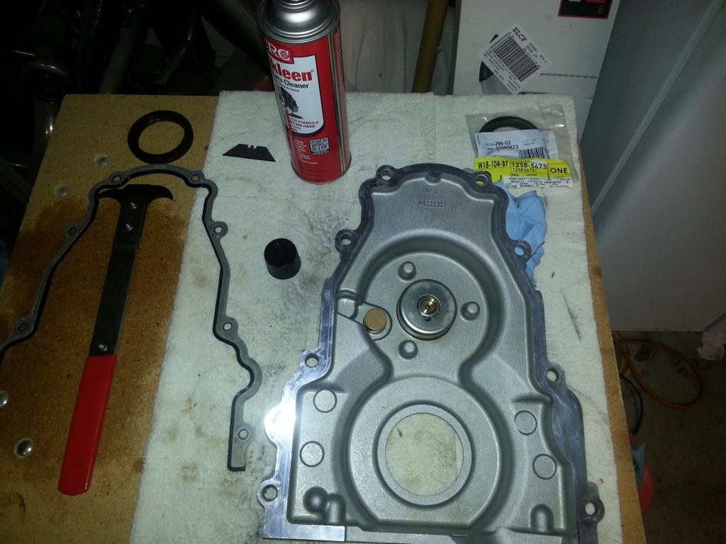 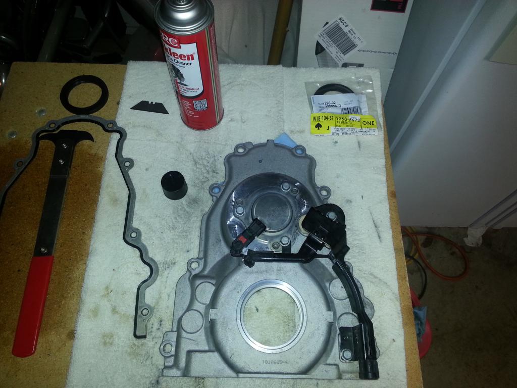 New Balancer seal: 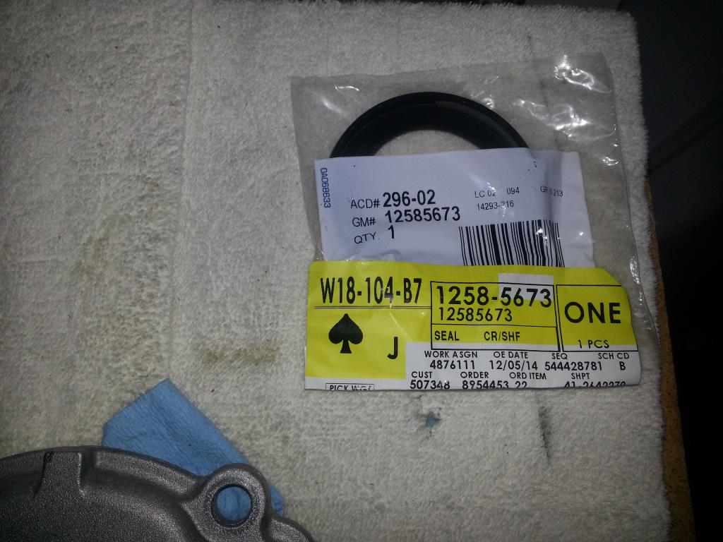 Cleaning the block in prep for timing cover: 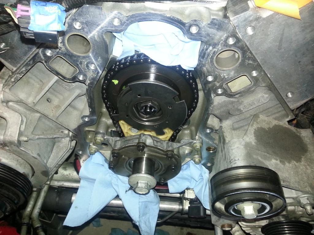 Ready to go!: 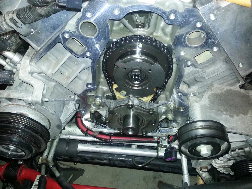 Seal in,, cover gasket held in with timing cover bolts: 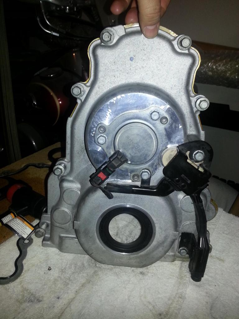 Special tool to install the cover so the balancer fits (SacCity now has these! https://www.saccitycorvette.com/AlignItTools.html):  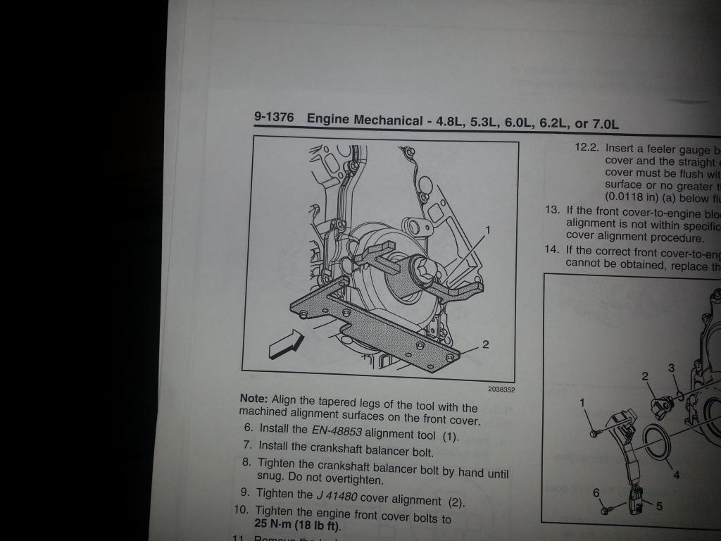 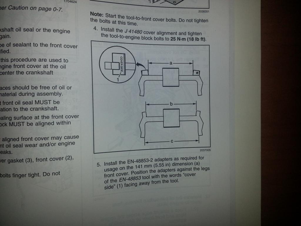 Ready to bolt up and hold the cover. The cover is just on and not tight yet (torque to 18 ft. lbs): 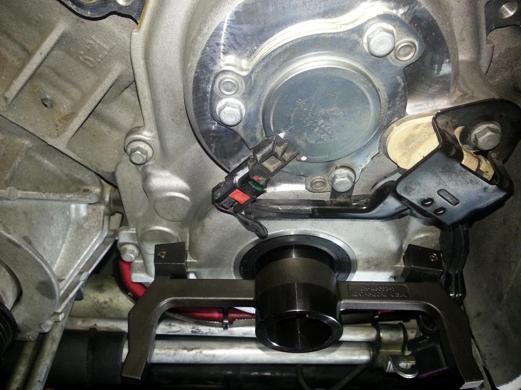 All done! Battery tray bolted back up and the connector for the sensor is re-connected: 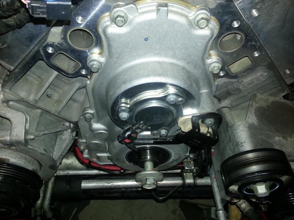 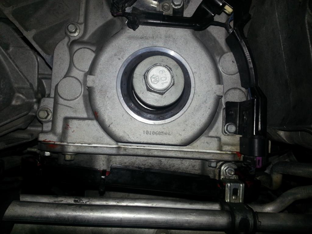 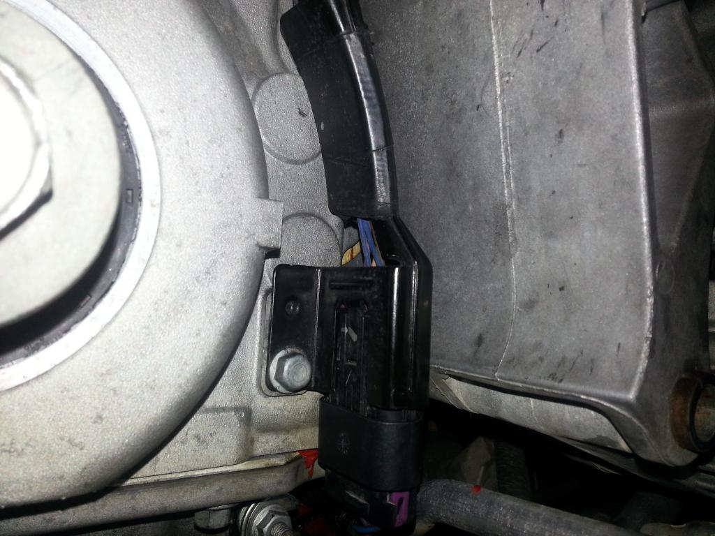 Ready for the next round! 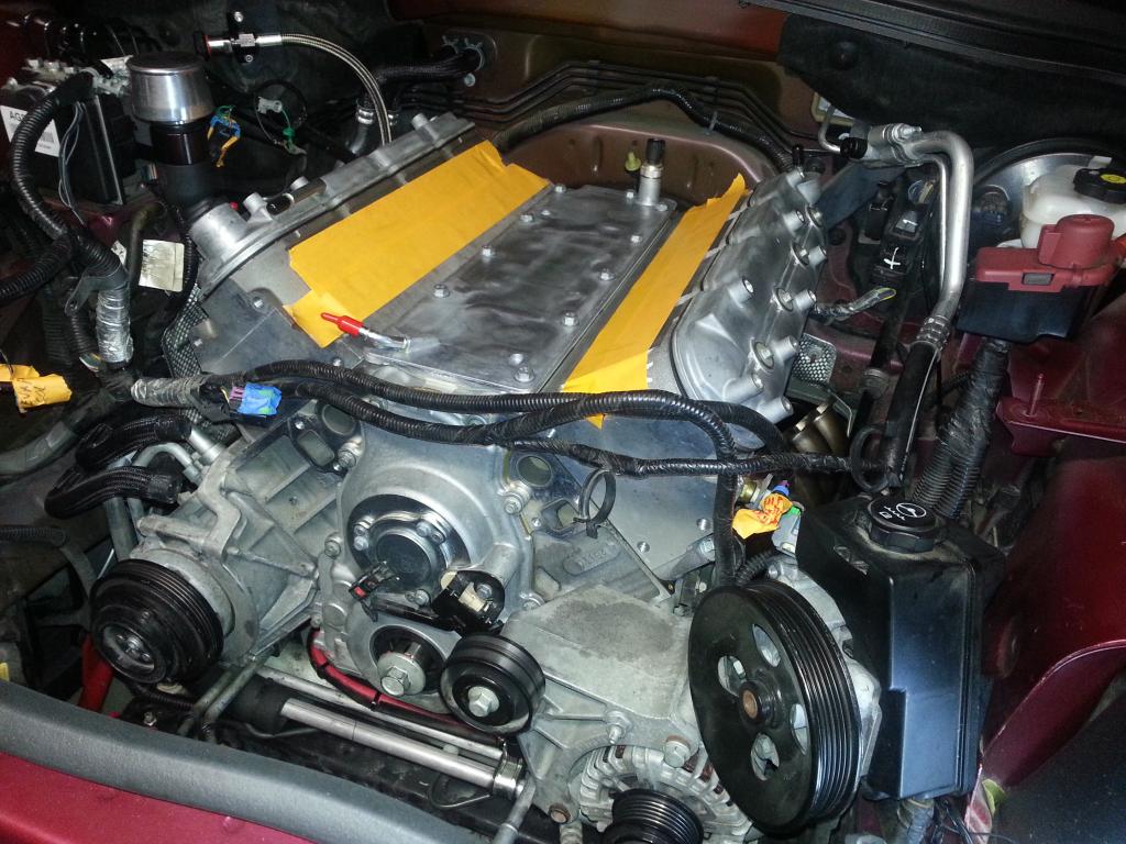 -Don Last edited by hammdo; 06-22-2019 at 10:15 AM. |
|
|
|
|
01-05-2015, 07:48 PM
|
#130 |
|
'It's an experiment'
Drives: [COTW 2/09/15] '11 GPI LSA SC Z/LE Join Date: May 2014
Location: Dallas TX
Posts: 8,709
|
Next, temp probe hooked up and the wire loom installed on driver's side:
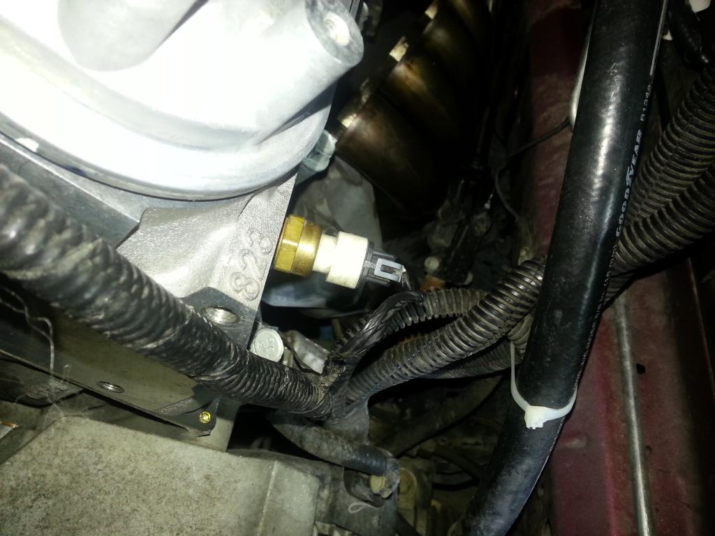 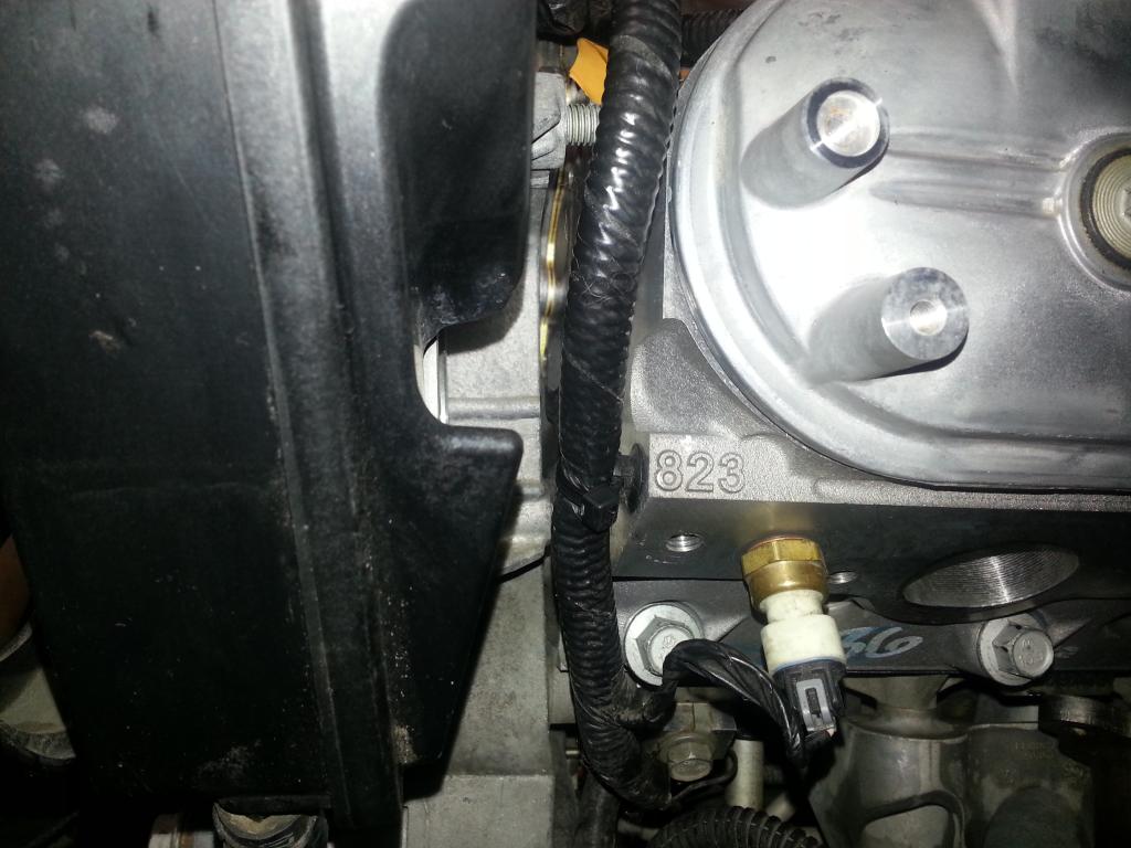 Alternator next (torque to 37 ft. lbs): 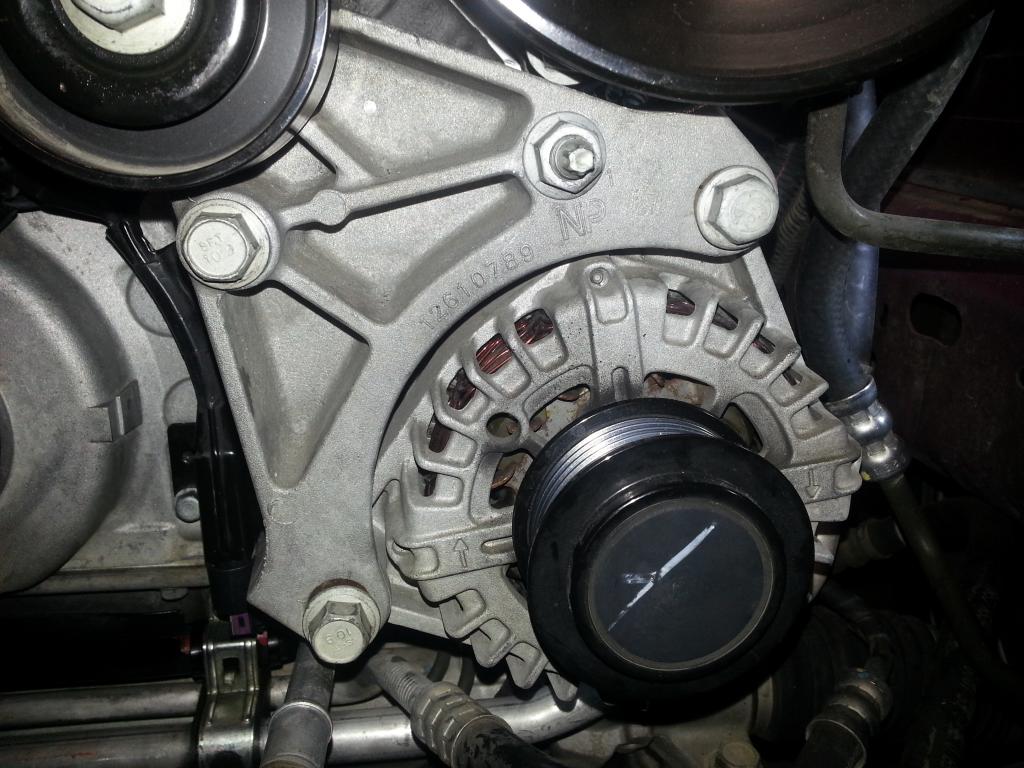 Power Steering (torque to 37 ft. lbs): 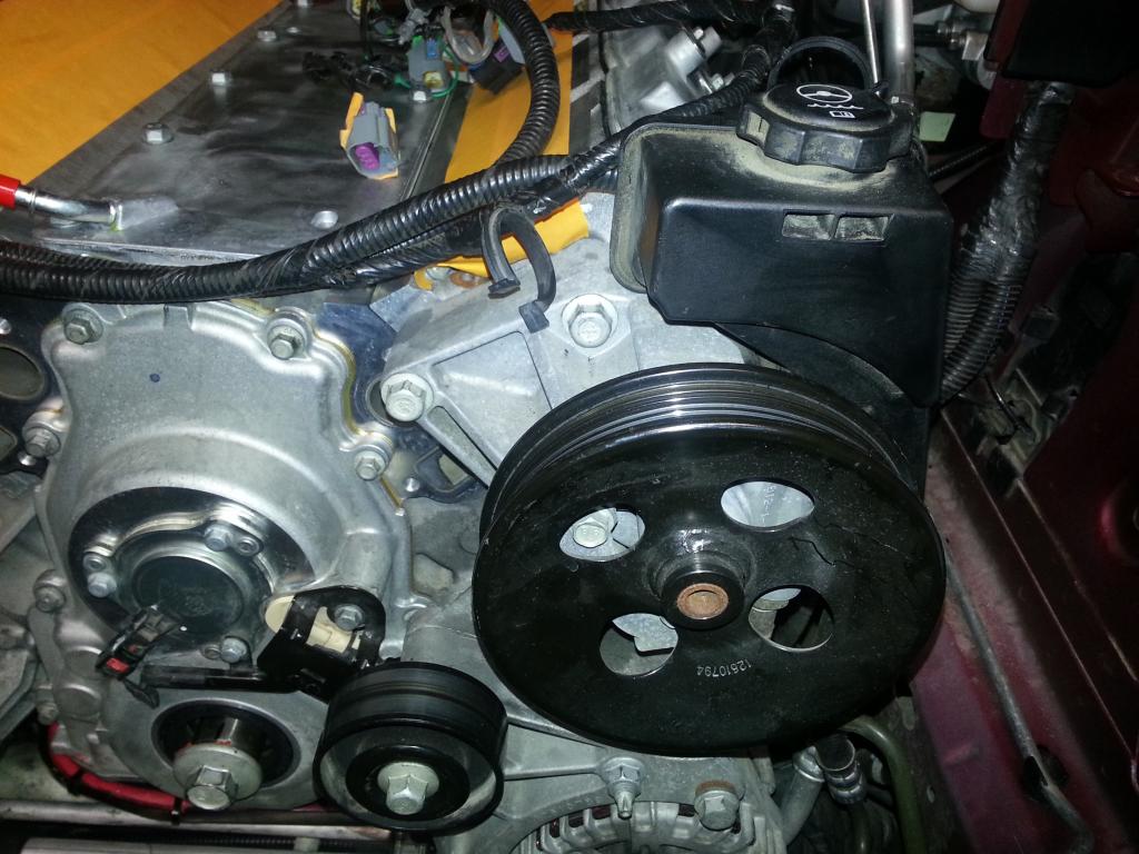 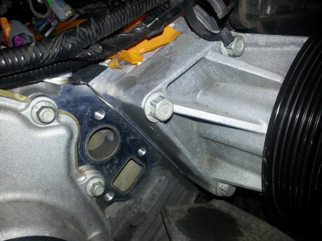 Now water pump with new gaskets (first torque to 11 ft. lbs, the second pass to 22 ft lbs): Gaskets: 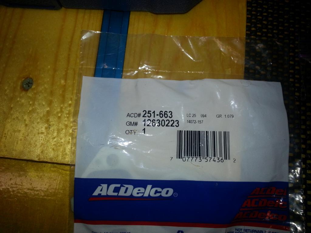 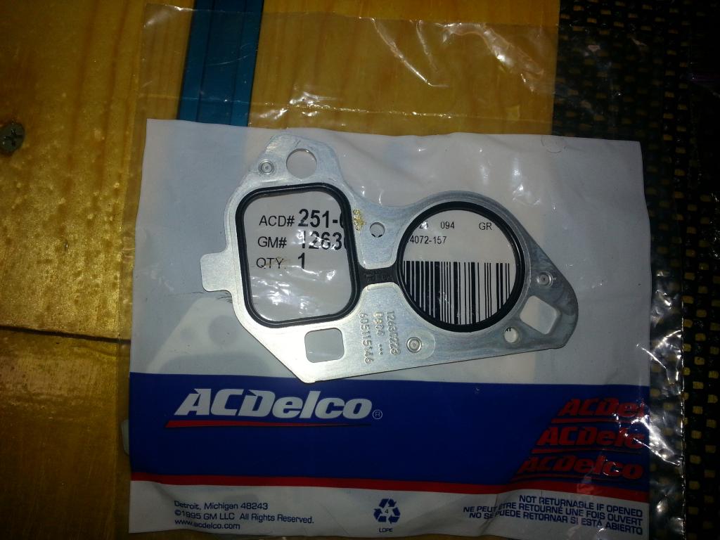 Ready to go!: 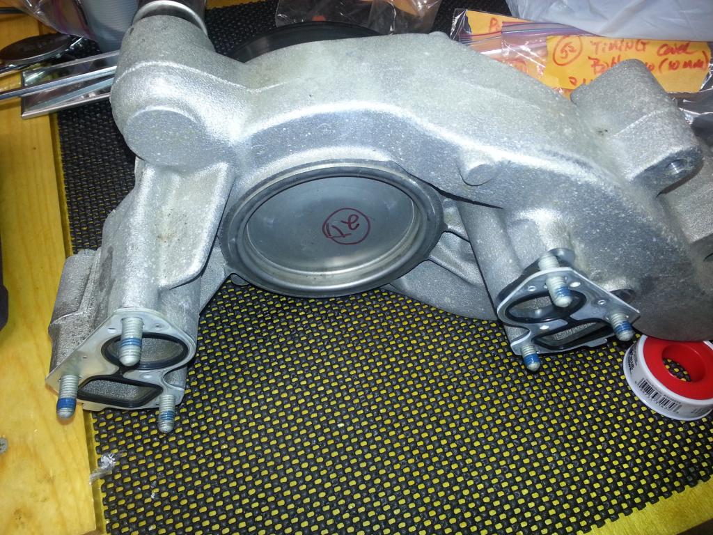 Installed!: 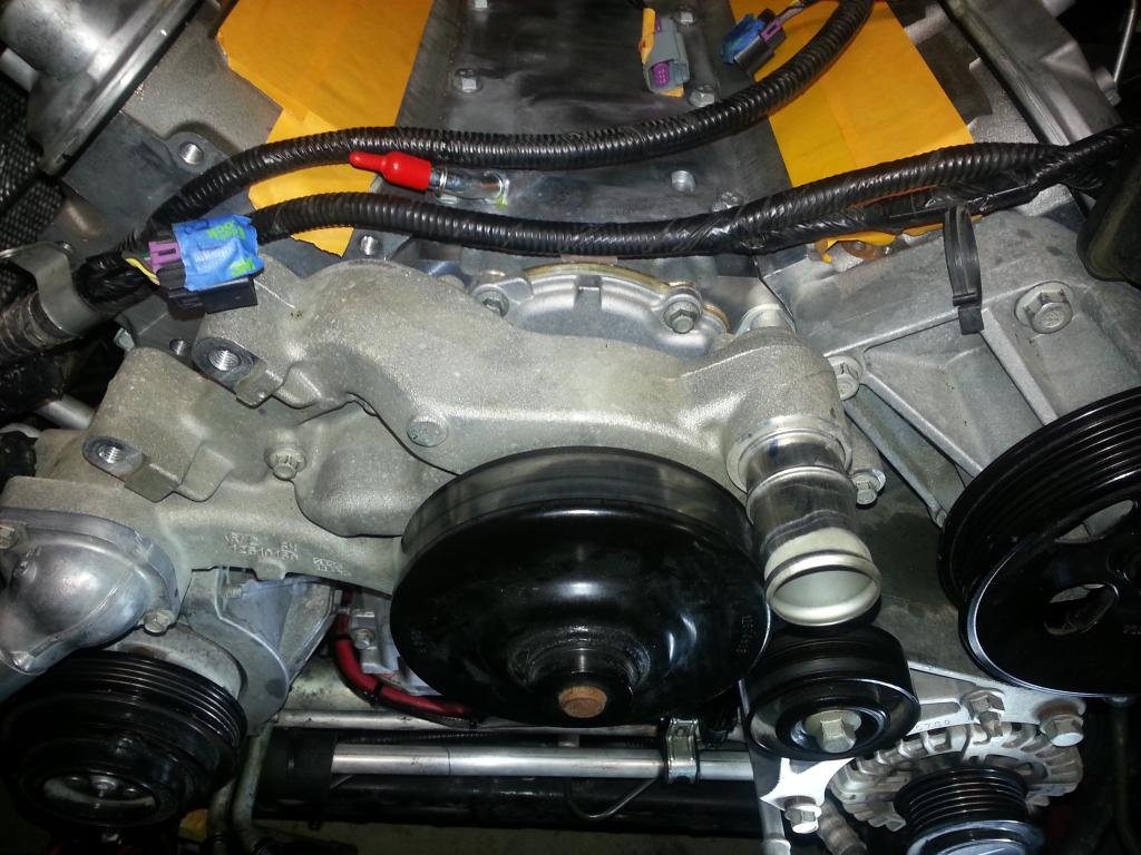 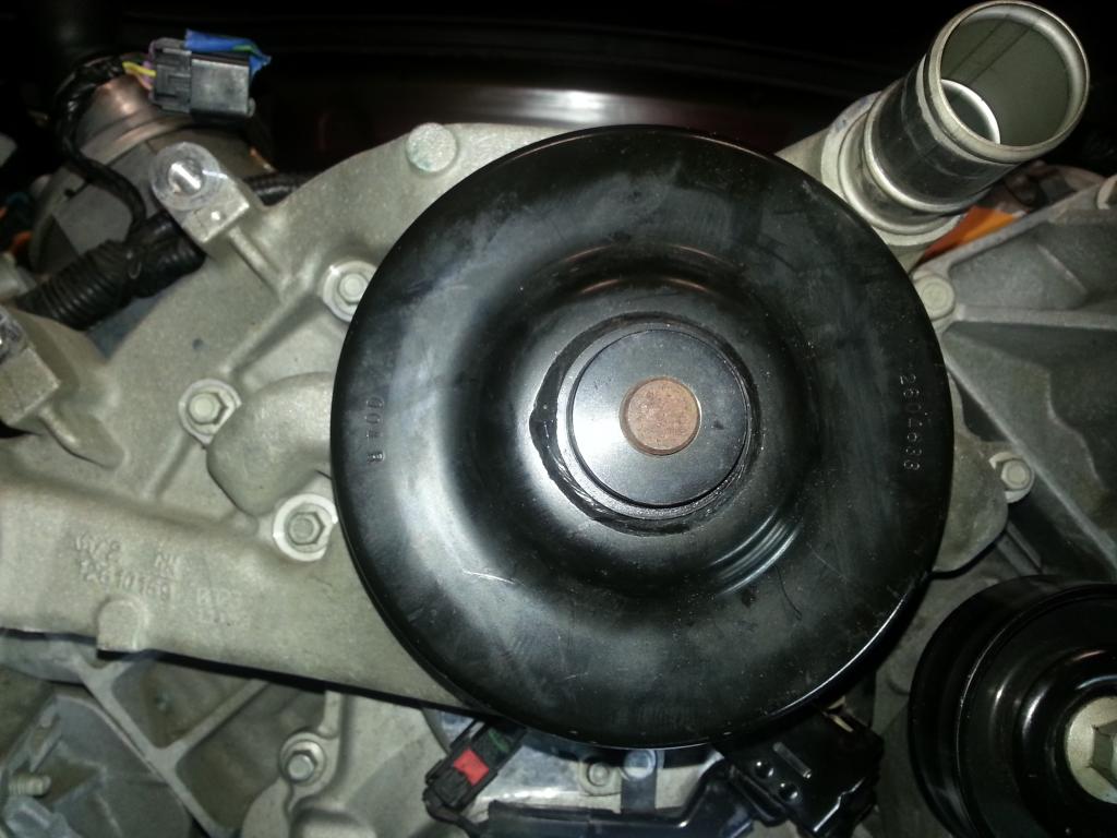 Now the heater hoses (remember the AGS lube!): 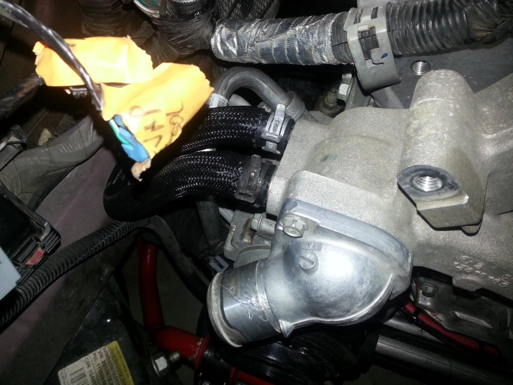 Rotated the engine to make sure nothing was binding now... Ready for the Balancer!:  -Don Last edited by hammdo; 07-02-2017 at 03:30 PM. |
|
|
|
|
01-05-2015, 09:54 PM
|
#131 |
|
'It's an experiment'
Drives: [COTW 2/09/15] '11 GPI LSA SC Z/LE Join Date: May 2014
Location: Dallas TX
Posts: 8,709
|
If ya got a pic of an L99 harmonic balancer, can you send it my way? Just need to confirm what I have is right:
http://www.amazon.com/ACDelco-126175...art/B004JBGC1W Rather be sure before I 'pin' this one... Thanks! -Don |
|
|
|
|
01-05-2015, 10:42 PM
|
#132 |
|
'It's an experiment'
Drives: [COTW 2/09/15] '11 GPI LSA SC Z/LE Join Date: May 2014
Location: Dallas TX
Posts: 8,709
|
OK, Rhino79 (Ryan) verified my balancer.
So, using the LS3 tool to install, installed the balancer and then checked the depth: Balancer: 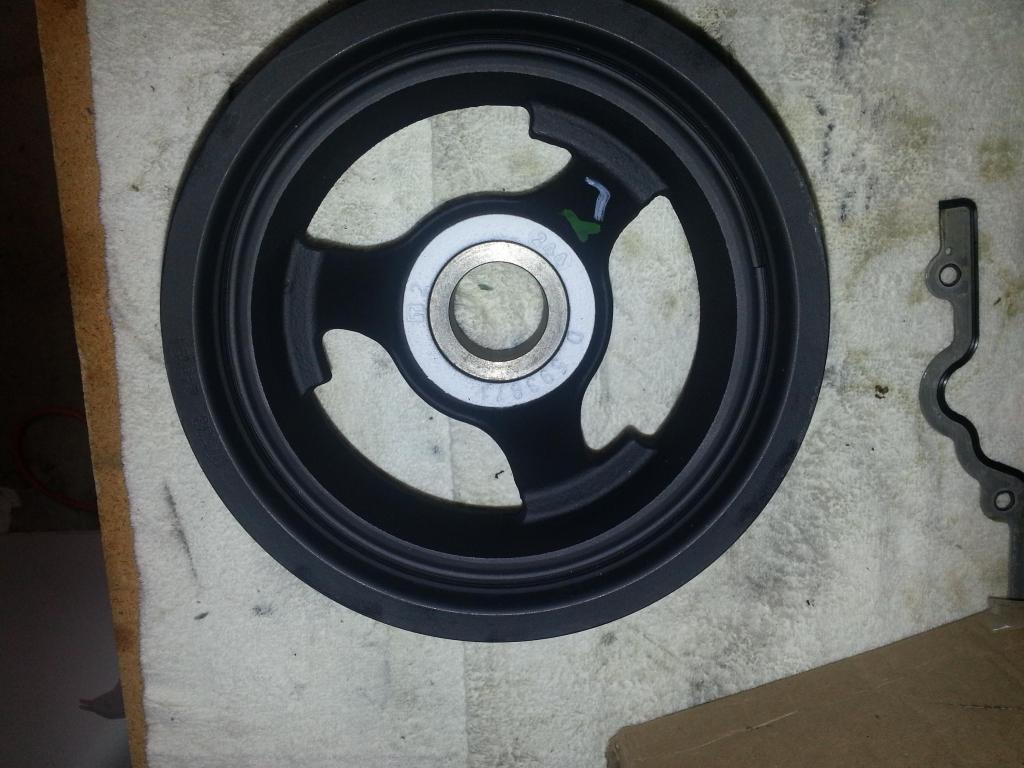 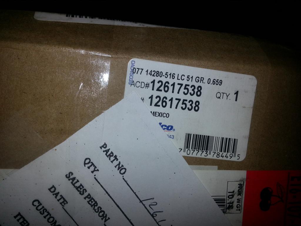 LS3 Install tool -- what a great tool to have: 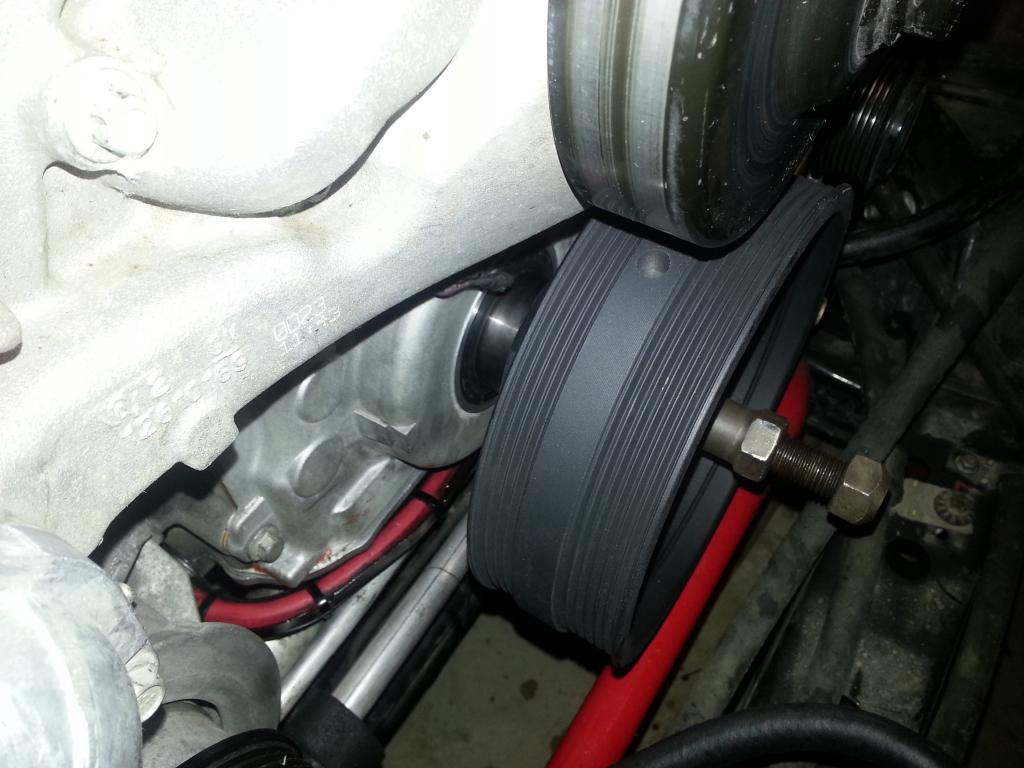 Using old bolt, torqued to 240 ft. lbs: 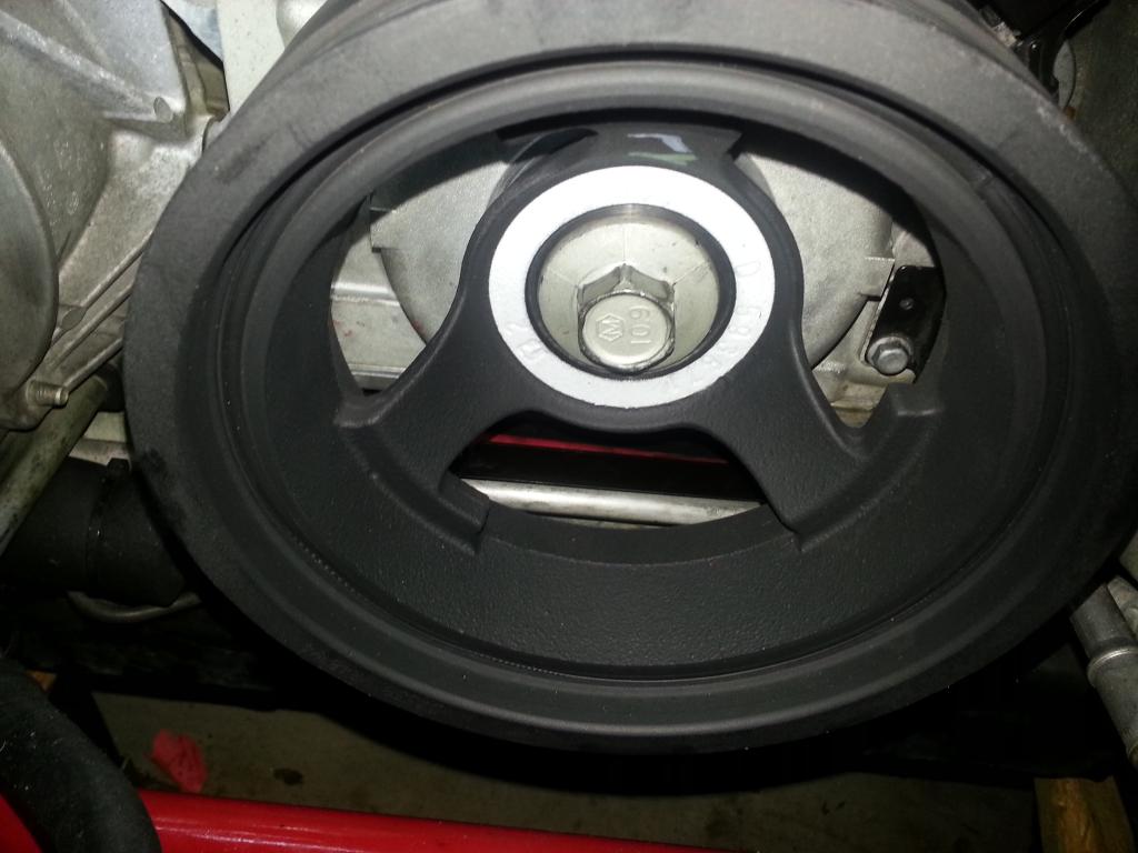 Validate depth: 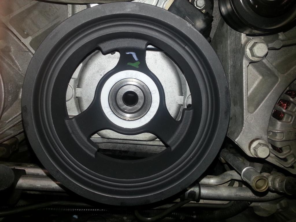 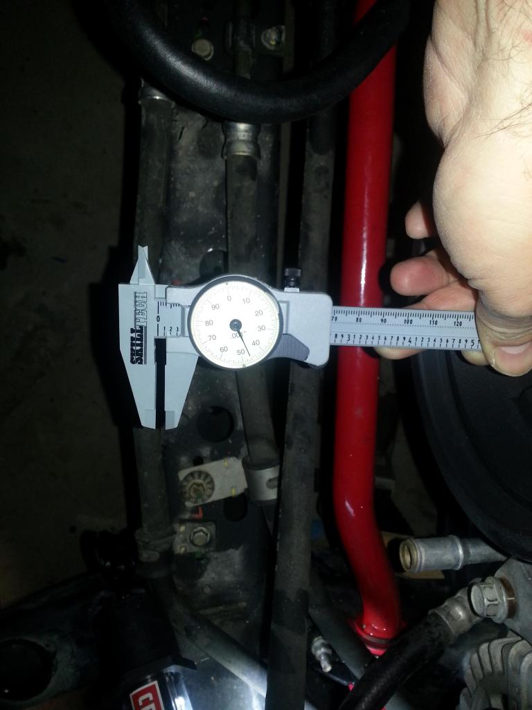 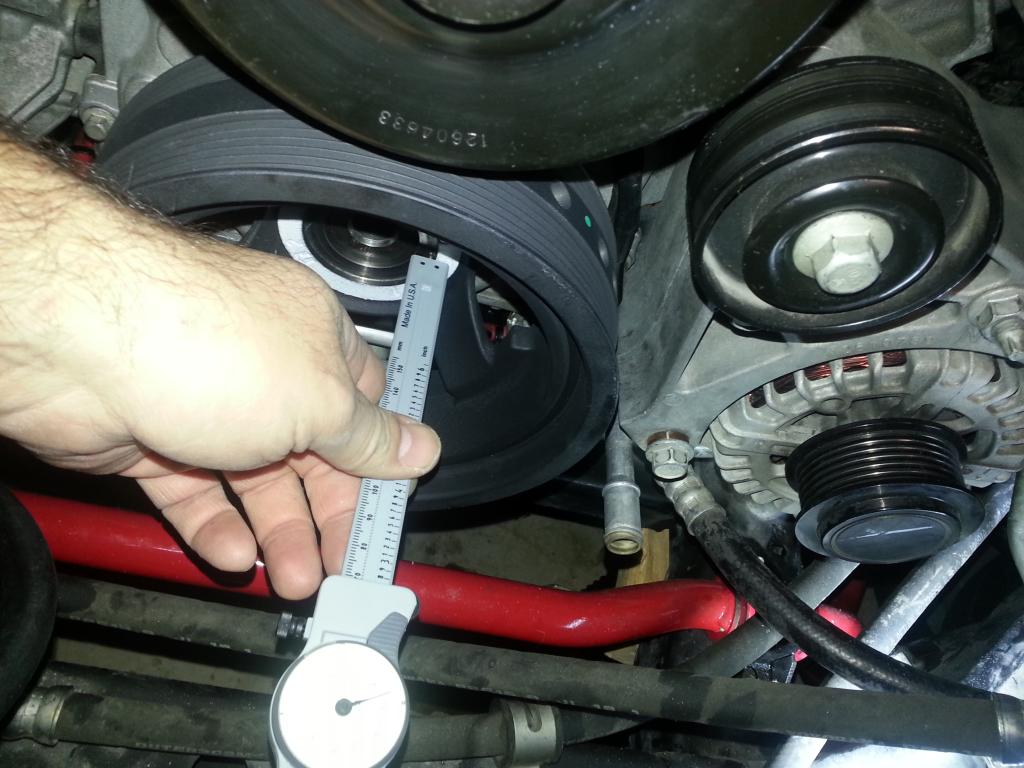 Woot! 0.146! In spec: 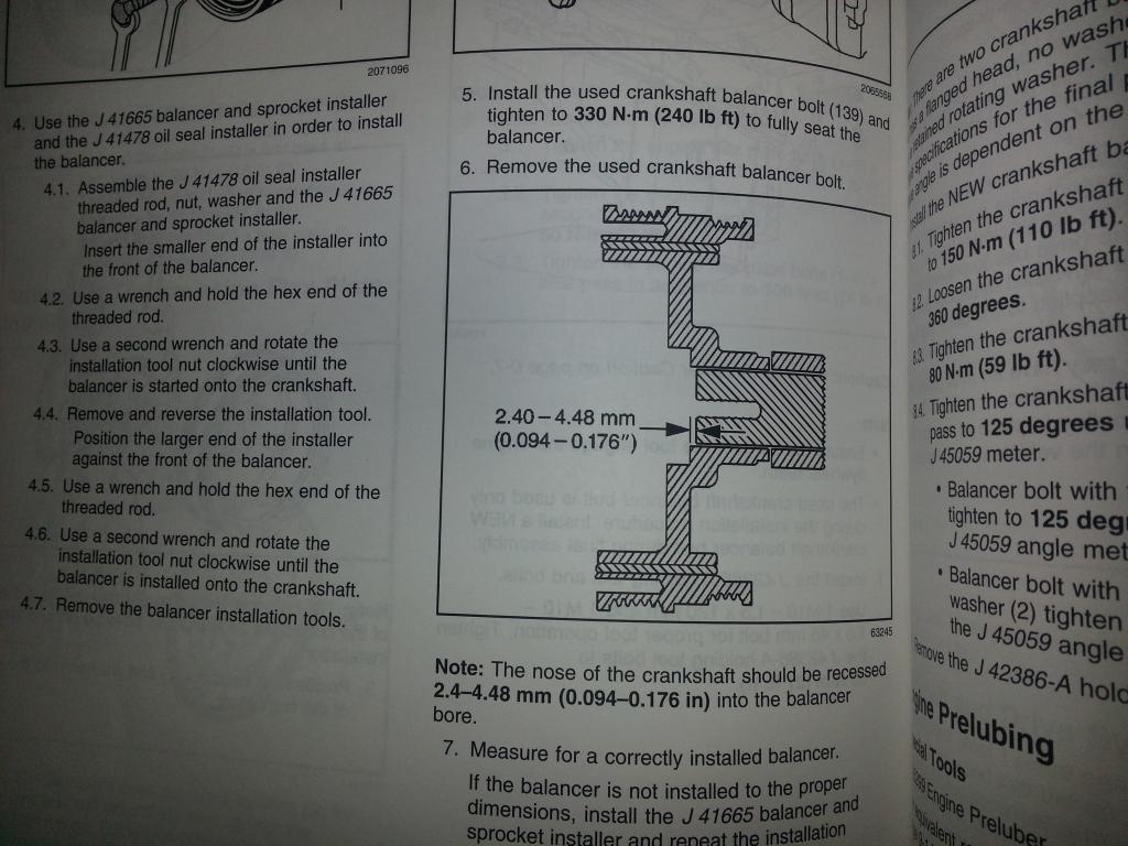 Next, I'll pin that puppy for the SC! -Don Last edited by hammdo; 07-02-2017 at 03:30 PM. |
|
|
|
|
01-06-2015, 02:49 PM
|
#133 |
|
'It's an experiment'
Drives: [COTW 2/09/15] '11 GPI LSA SC Z/LE Join Date: May 2014
Location: Dallas TX
Posts: 8,709
|
Well, before I pin the crank, there seems to be some debate on the dog bone vs tensioner for VVT -- I'm hearing where VVT should have the tensioner -- where others have replaced it for the dog bone. It was recommended to me to use the dog bone from a couple of reputable builders so before I pin this thing, I doing a bit more research to verify. I'm asking a couple of other builders and hope to know today -- so far, the one's I've asked that recommended the dog bone see no issue with it and VVT...
Thanks! -Don |
|
|
|
|
01-06-2015, 08:52 PM
|
#134 |
|
'It's an experiment'
Drives: [COTW 2/09/15] '11 GPI LSA SC Z/LE Join Date: May 2014
Location: Dallas TX
Posts: 8,709
|
Getting the SC manifold ready. ADM's kit already removed the locating pin so all I really need to do now is drill out the intake gasket rivets, get the gaskets ready, and use some vacuum grease so I can 'slide' the manifold as needed to install the intake bolts.
I'll be getting the wiring going first while nothing is in the way. Will be using the 'wrap' vs 'pig tail' soldering approach for the wires along with 'alternating' lengths -- which is the usual technique... Working through the Dog Bone vs LS3/L99 Tensioner debate... More to come... -Don |
|
|
|
|
01-06-2015, 09:36 PM
|
#135 |
|
'It's an experiment'
Drives: [COTW 2/09/15] '11 GPI LSA SC Z/LE Join Date: May 2014
Location: Dallas TX
Posts: 8,709
|
OK, installing some of the wiring and putting the 'tags' on:
Brake Booster connector: 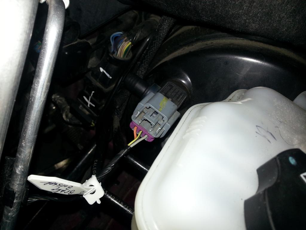 Driver's side top O/2 Connector (for the O/2 Sensor on the header) back on the driver's side head (rear): 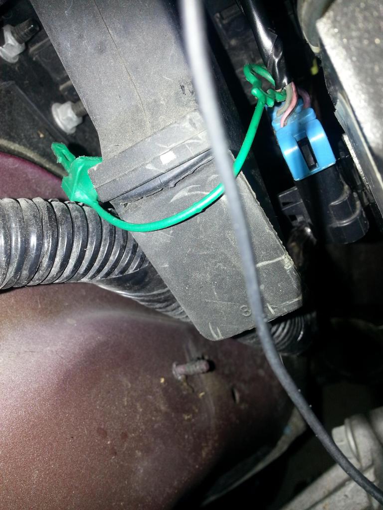 Ground re-installed on the driver's side head (near Oil Pressure Sensor):  Valve installed on rear of passenger's head: 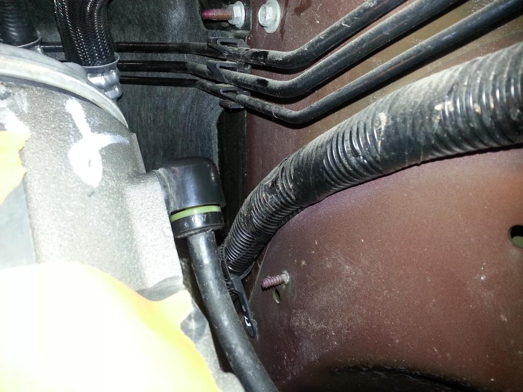 Tagged a few more items in prep for wire extensions for the super charger... -Don Last edited by hammdo; 07-02-2017 at 03:29 PM. |
|
|
|
|
01-07-2015, 11:44 AM
|
#136 |
|
'It's an experiment'
Drives: [COTW 2/09/15] '11 GPI LSA SC Z/LE Join Date: May 2014
Location: Dallas TX
Posts: 8,709
|
Setting up to do a test fit of the supercharger manifold to verify it clears the DOD Delete (LS3) valley cover and the vent - I notice on some conversions (LSA Supercharger) that I don't see a vent underneath the SC manifold -- want to confirm first...
-Don |
|
|
|
|
01-07-2015, 04:44 PM
|
#137 |
|
'It's an experiment'
Drives: [COTW 2/09/15] '11 GPI LSA SC Z/LE Join Date: May 2014
Location: Dallas TX
Posts: 8,709
|
OK, during lunch worked a couple of test fits.
First, the bracket that was on the passenger's head (held the wire loom and ground cable). had to be removed. We'll need to relocate the ground too. First, removed the bracket from the wire harness: 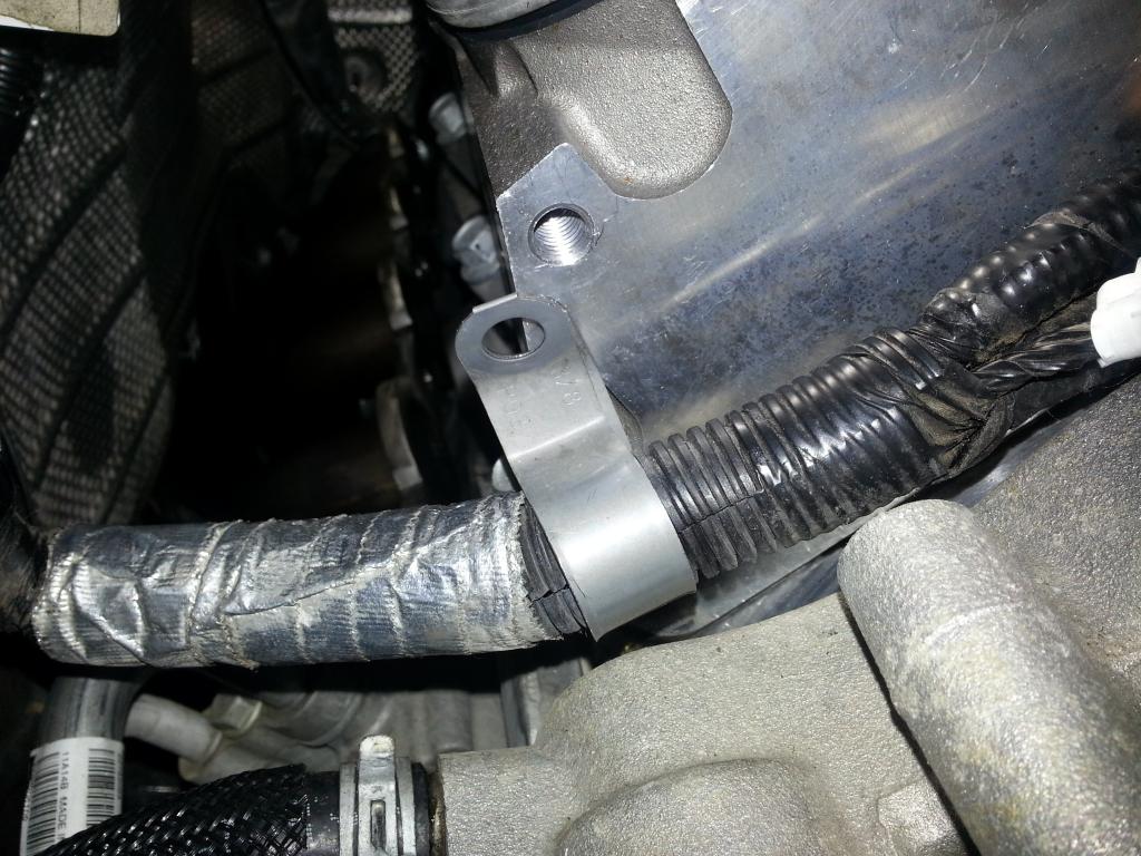 Removed (note the bolt hole on the head near the left. This is where the bracket and ground was on the L99 setup): 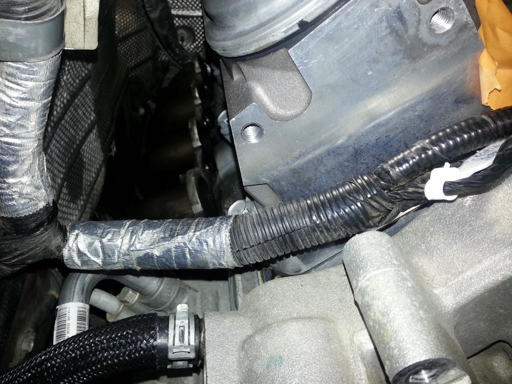 Loom: 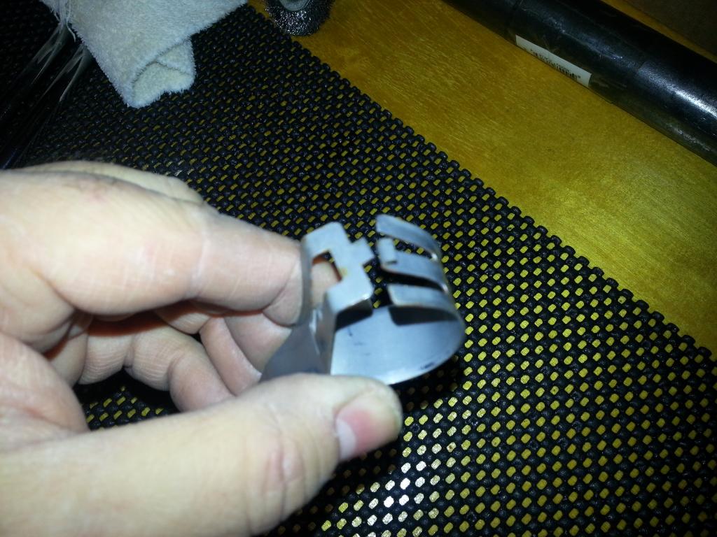 Now, test fit the pulley assembly (custom made and I believe patent pending by ADM!) and the Tensioner: Tensioner (note where we have to put the wiring path now): 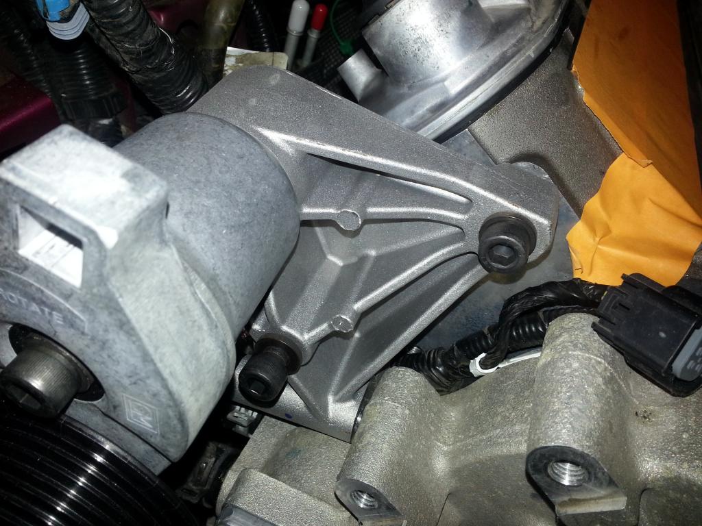 Really need to tuck the wires:  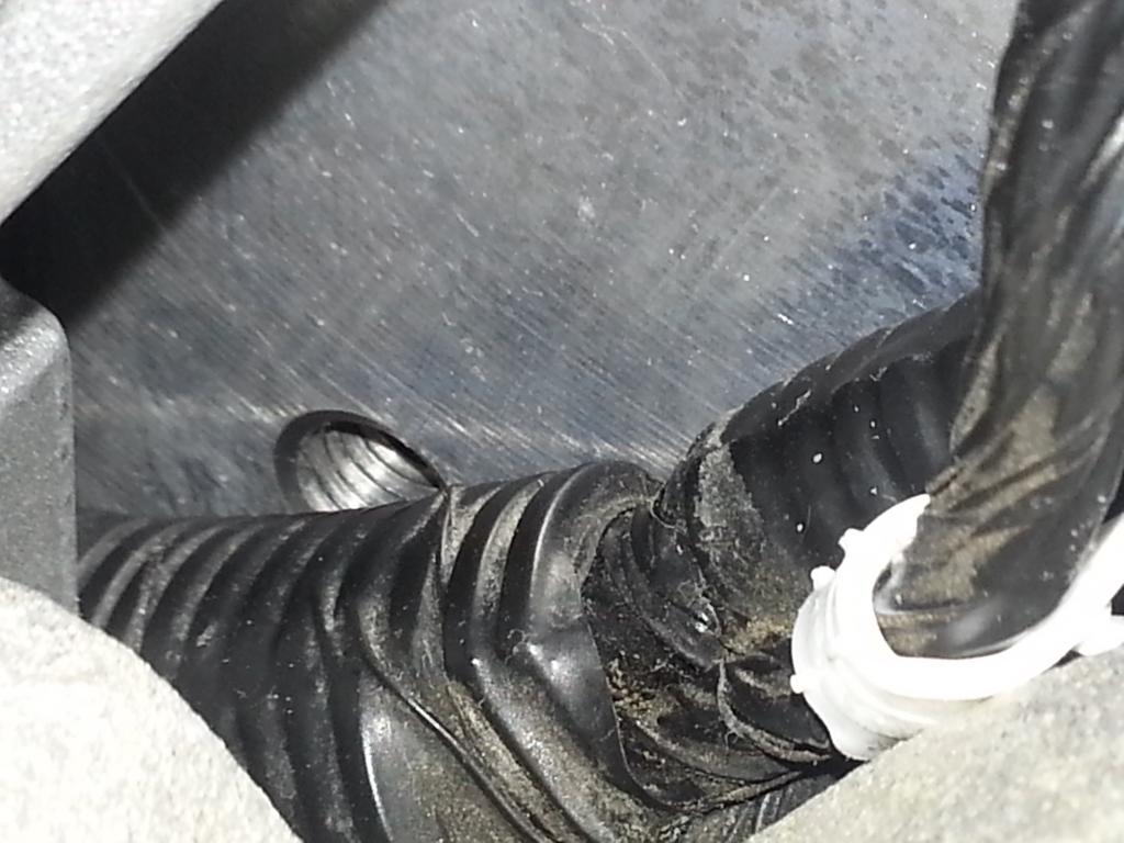  ADM's custom pulley assembly. Note we use the original bolt holes and have to remove the water pump bolt (middle of the three on the passenger's side of the pump): 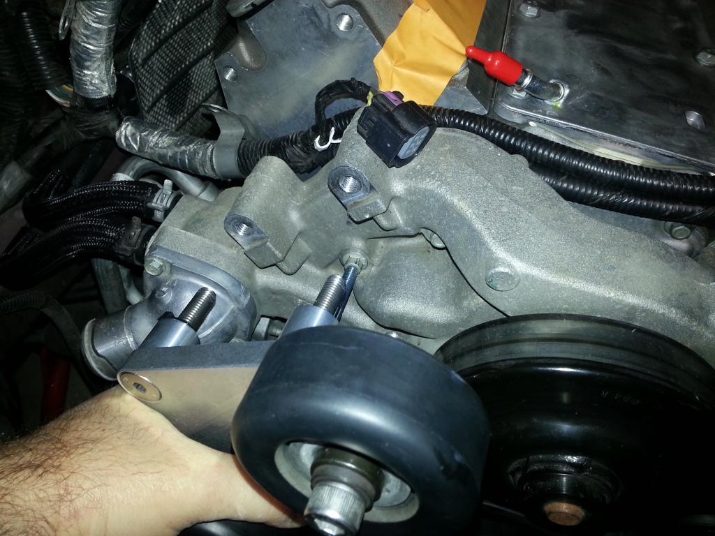 Now, we need to test the 'new' location for the body ground cable. For the L99, it was on the head here:  Manual:  For the ZL1/LSA, its bolted on the head still, but on the 'manifold' side: 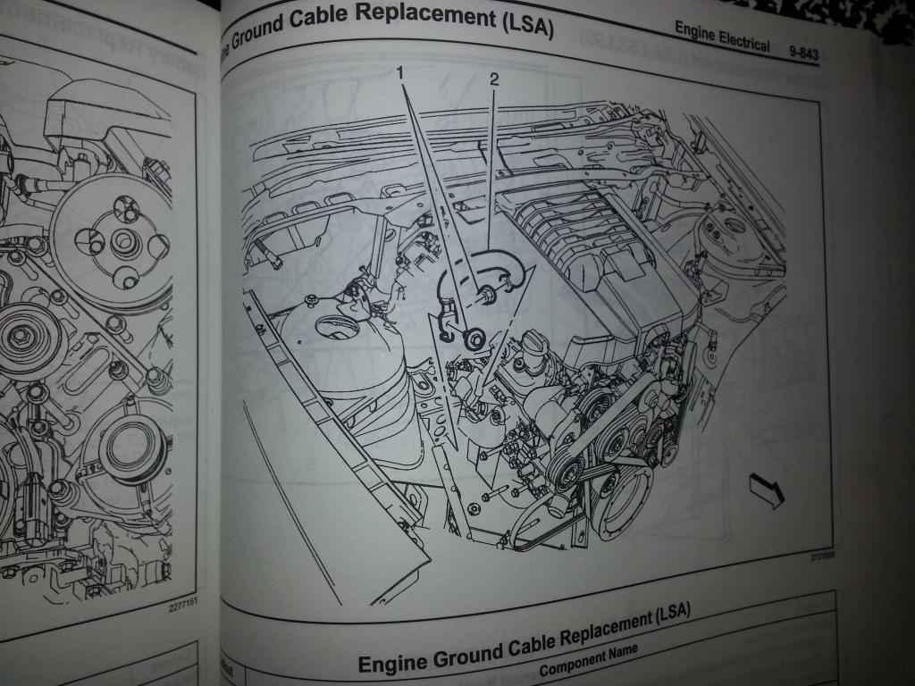 So, same cable, different side. I reused the original ground cable stud: 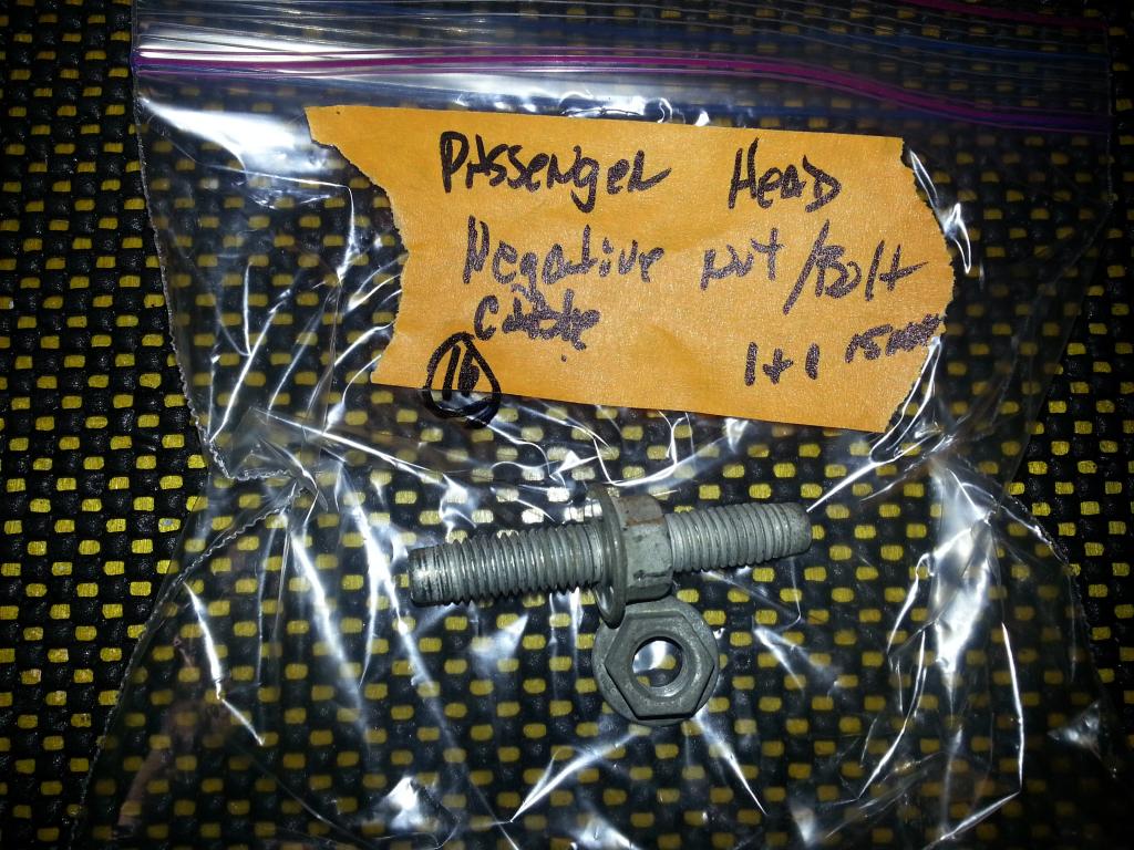 And test the fit here:  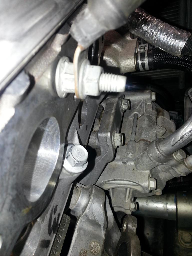 Good to know the LSA had this location! 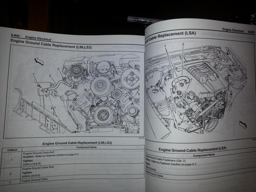 At least I was able to leverage the 2011 and 2013 GM manuals (I have the 2011 for my 2SS and 2013 for the ZL1/LSA/SC -- really helps!). I will have to test the fit with the headers. From the looks of things, I'll have to grind the stud 'washer' down a bit so things will line up. I do know the other ground that was on the L99 head (near the middle) had no issues with the headers... More to come -Don Last edited by hammdo; 07-02-2017 at 03:29 PM. |
|
|
|
|
01-07-2015, 05:46 PM
|
#138 |
|
'It's an experiment'
Drives: [COTW 2/09/15] '11 GPI LSA SC Z/LE Join Date: May 2014
Location: Dallas TX
Posts: 8,709
|
OK, with an update from Andy @ ADM, I'll need to trim the stud length about 3 threads to prevent it from bottoming out (which I did notice during the test fit) and from my own observations using a dial caliper, I was able to determine the 'washer' part of the stud head is 0.015 wider than the dipstick tube bolt head so that will also need to be ground down so it will fit like the dipstick did beforehand.
Dipstick installed in the L99 before teardown as a reference (before it all began): 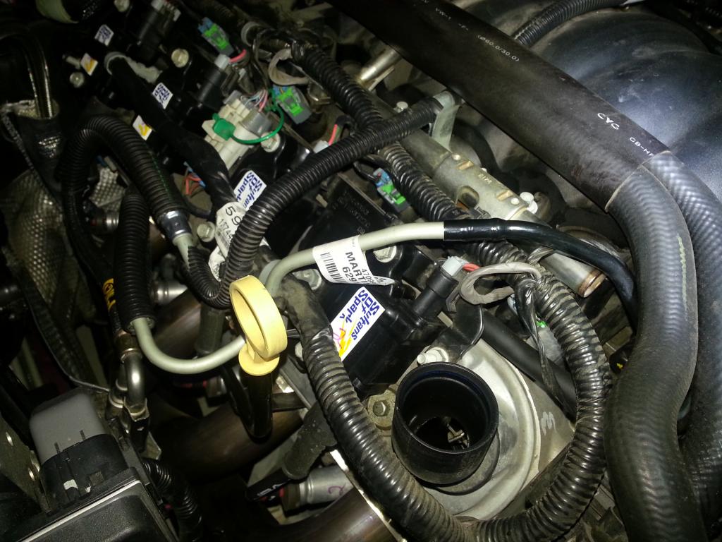 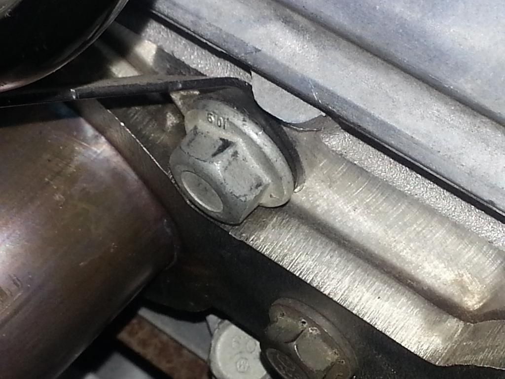 The ZL1 (for the ground and body ground -- note they moved the dipstick location too): 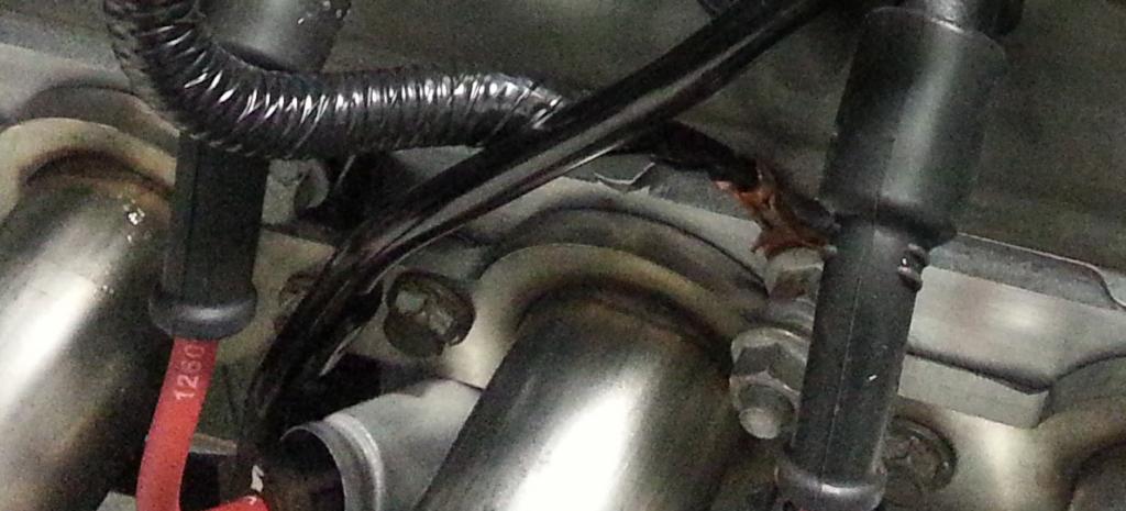 -Don Last edited by hammdo; 07-02-2017 at 03:28 PM. |
|
|
|
|
01-07-2015, 10:04 PM
|
#139 |
|
'It's an experiment'
Drives: [COTW 2/09/15] '11 GPI LSA SC Z/LE Join Date: May 2014
Location: Dallas TX
Posts: 8,709
|
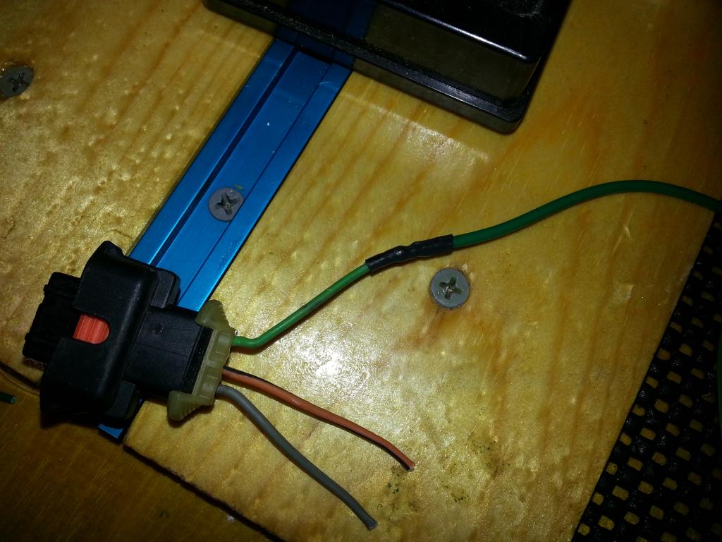
Well, I didn't have time for the sc test fit (some setup to do) so I did the throttle body wiring.
The color code for the kit is Kit Color ->TB Connector Color Blue -> Brown (Dark) Orange -> Lt. Brown Yellow -> Yellow Purple -> Purple Green -> Green White -> Gray Kit wire: 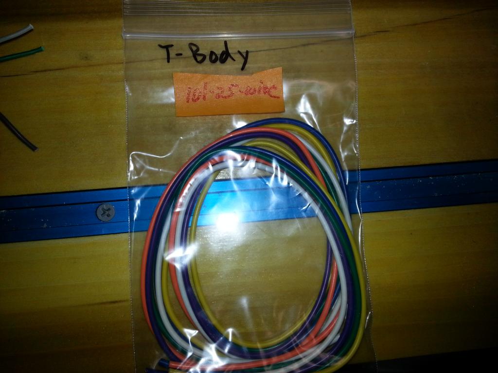 So with that in mind, I stripped back the existing electrical tape to expose the connector wires. I made sure that I left enough on both sides of the cut to wrap and solder:  Cut: 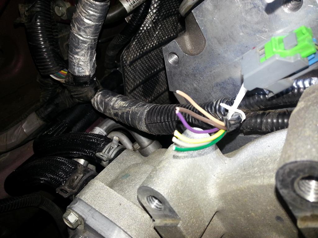  Now, using Rosin Core solder (60/40), I began stripping the wire and soldering it. I also used the 'heat shrink tubes' to cover up the solder, then wrapped the sections of wire in electrical tape -- then finished off with the kit supplied wire cover: This is a 'wrap' type connection for soldering: 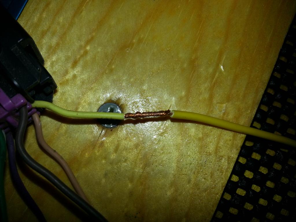 Soldered with heat shrink tube: 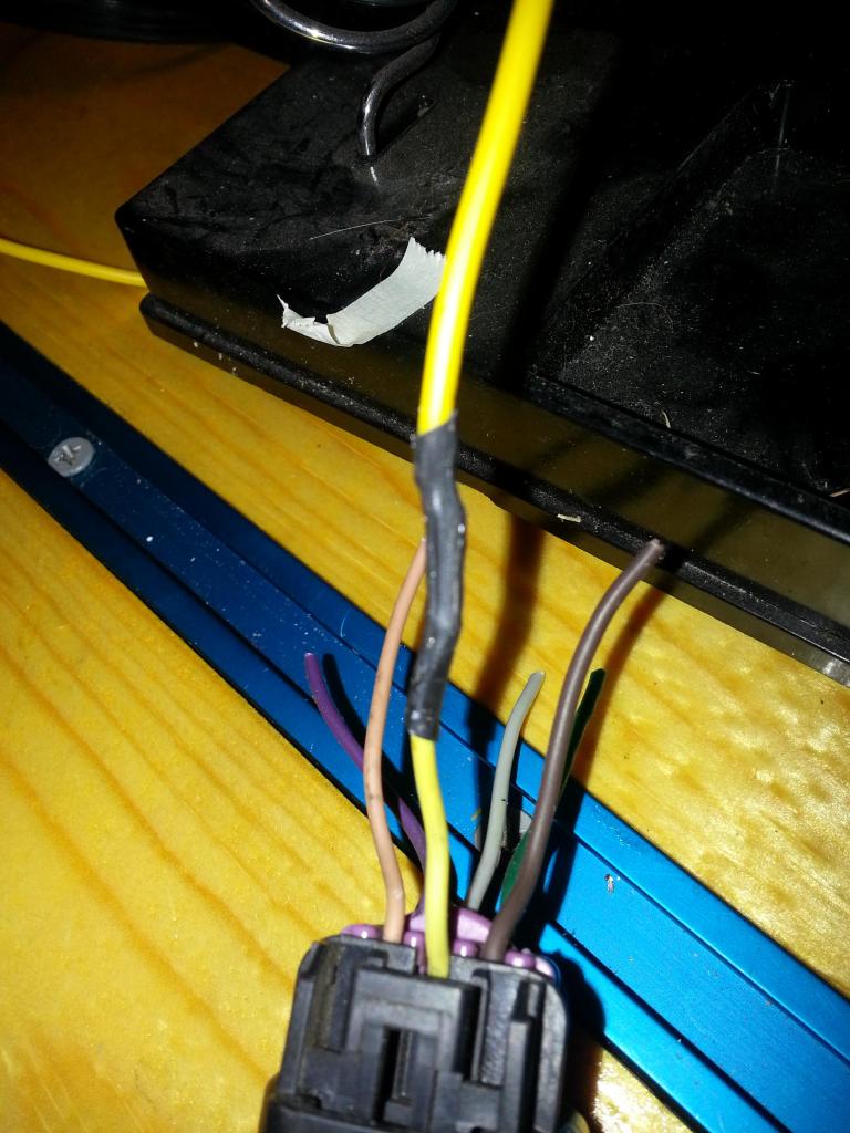 Prepped for soldering on the car (before adding the wire sleeve) Make sure, before you solder the wires on the car, to add the heat shrink tubing and the wire cover first -- or you'll be stuck ;o) 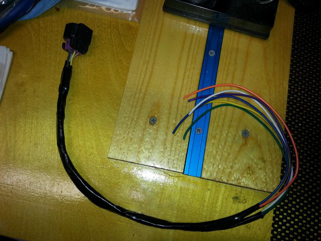 Soldering on the car with heat shrink tube also: 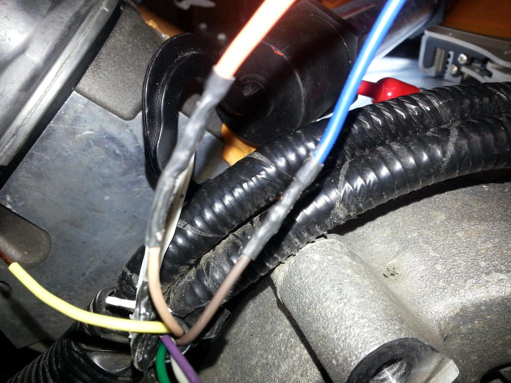 All together now! ends of the shield are taped and tye-wrapped: 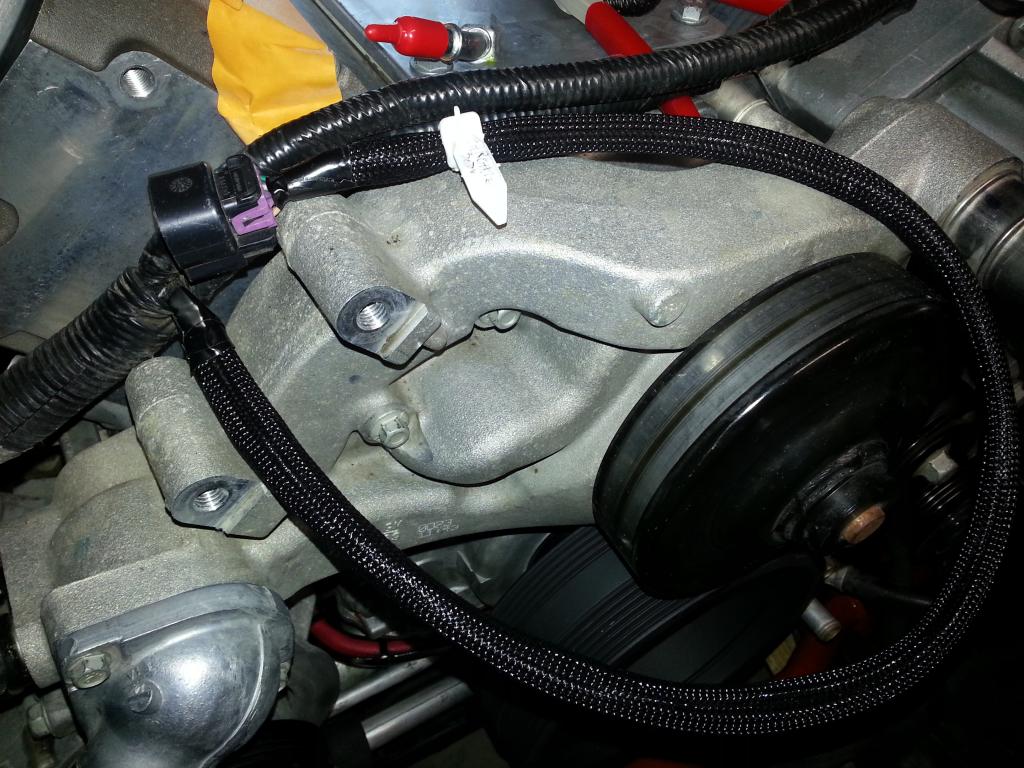 Before: After: Next, I'll do the MAP and EVAP connectors... -Don Last edited by hammdo; 07-02-2017 at 03:28 PM. |
|
|
|
|
01-08-2015, 01:02 AM
|
#140 |
|
'It's an experiment'
Drives: [COTW 2/09/15] '11 GPI LSA SC Z/LE Join Date: May 2014
Location: Dallas TX
Posts: 8,709
|
Finished the MAP sensor wiring:
 Used this for the shielding (McMaster-Carr): 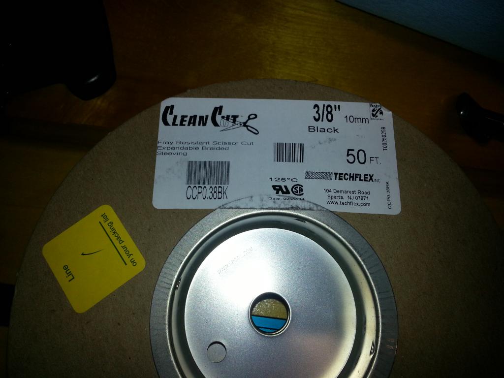 Complete: 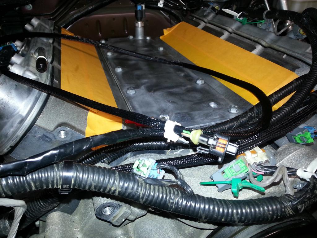 EVAP: 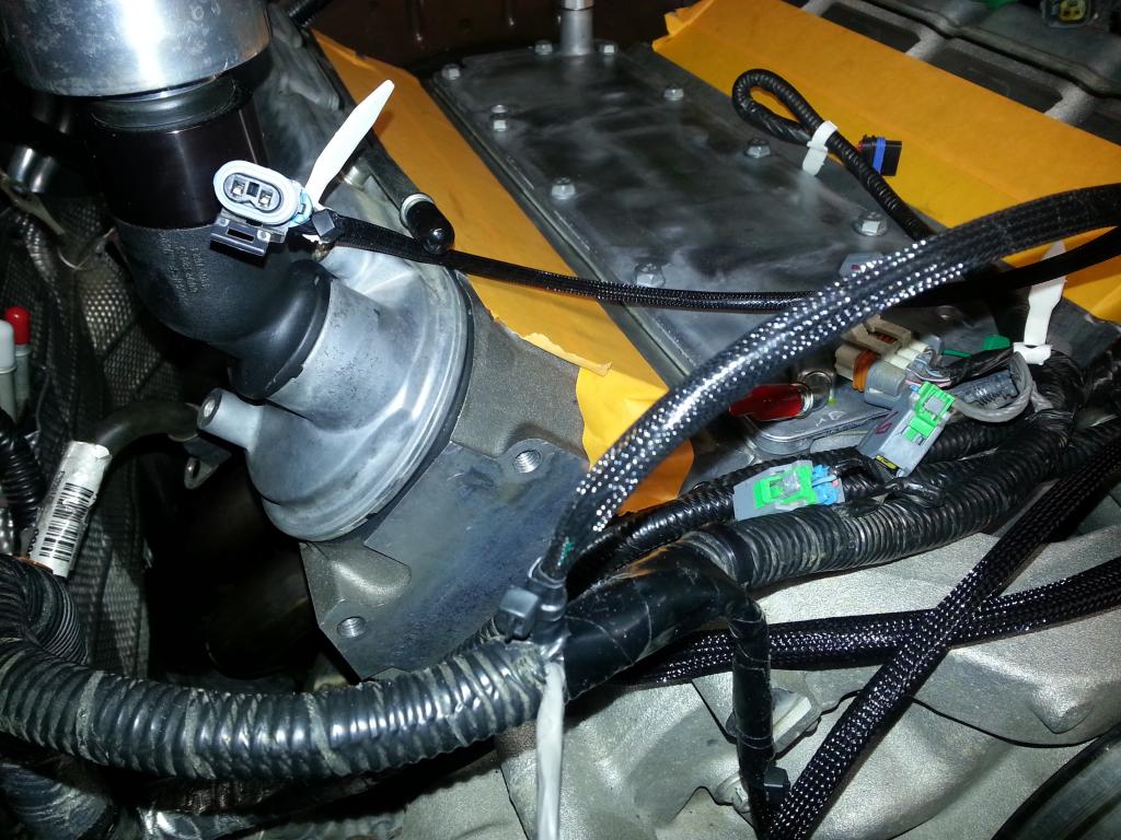 That part of the SC kit from ADM is done! More to come... -Don Last edited by hammdo; 07-02-2017 at 03:27 PM. |
|
|
|
|
|
|
|
 |
|
|


