Camaro5 Chevy Camaro Forum / Camaro ZL1, SS and V6 Forums - Camaro5.com
 
Phastek Performance
Go Back   Camaro5 Chevy Camaro Forum / Camaro ZL1, SS and V6 Forums - Camaro5.com > Technical Camaro Topics > Camaro DIY & HOW-TO instructions & discussions


Reply
 
Thread Tools
Old 10-24-2011, 08:30 PM   #29
Eric Baker

 
Drives: Black/Black 2SS/RS 6M
Join Date: Mar 2010
Location: Boston MA
Posts: 987
Uh oh...
Eric Baker is offline   Reply With Quote
Old 10-24-2011, 08:31 PM   #30
SUX2BU
Quit being a pu$$y
 
SUX2BU's Avatar
 
Drives: FAST
Join Date: Jan 2011
Location: Sachse TX (DFW)
Posts: 5,825
Quote:
Originally Posted by lexlueger View Post
I tried this for a 2-step and I think I fried some "stuff". I have no power windows,door locks, srs light, service air bag in the DIC,stabilitrack, no radio, etc
Check the fuses.
SUX2BU is offline   Reply With Quote
Old 10-24-2011, 10:07 PM   #31
lexlueger


lexlueger's Avatar
 
Drives: V10 BMW M5, Supercharged 2SS/RS
Join Date: Jun 2010
Location: Charlotte NC /Brooklyn NY
Posts: 2,305
Quote:
Originally Posted by SUX2BU View Post
Check the fuses.
I did. under hood, driver door and trunk.
__________________
MAST 416 STROKER: STAGE 3 TVS 2300
CUSTOM CAM
TPIS 102 TB
IW 8 RIB PULLEY W/ OD COG REARS
NX EXPRESS/NANO KIT

KDI HEAT EXCHANGER/ROTOFAB RESERVOIR
CIRCLE D 2800 TC/FLEX PLATE/ADM TRANS COOLER
DSS DRIVESHAFT/1400 HP AXLES
EATON TRUETRAC -LPE 3.27 GEARS
DYNATECH HEADERS/MAGNAFLOW EXHAUST
SQUASH RETURN STYLE FS ID 850's E85/ FLEXFUEL
BMR/EIBACH SUSPENSION

KILL MODE, ON.


lexlueger is offline   Reply With Quote
Old 03-26-2012, 10:34 PM   #32
Three of Swords
 
Three of Swords's Avatar
 
Drives: 2011 IBM 1SS/RS L99
Join Date: Mar 2011
Location: MI
Posts: 300
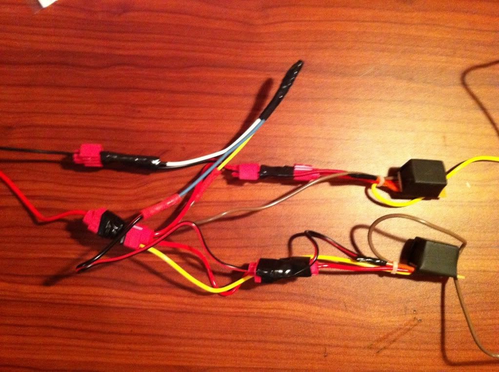
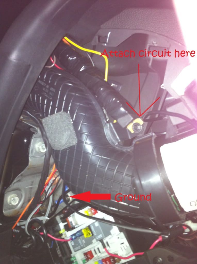
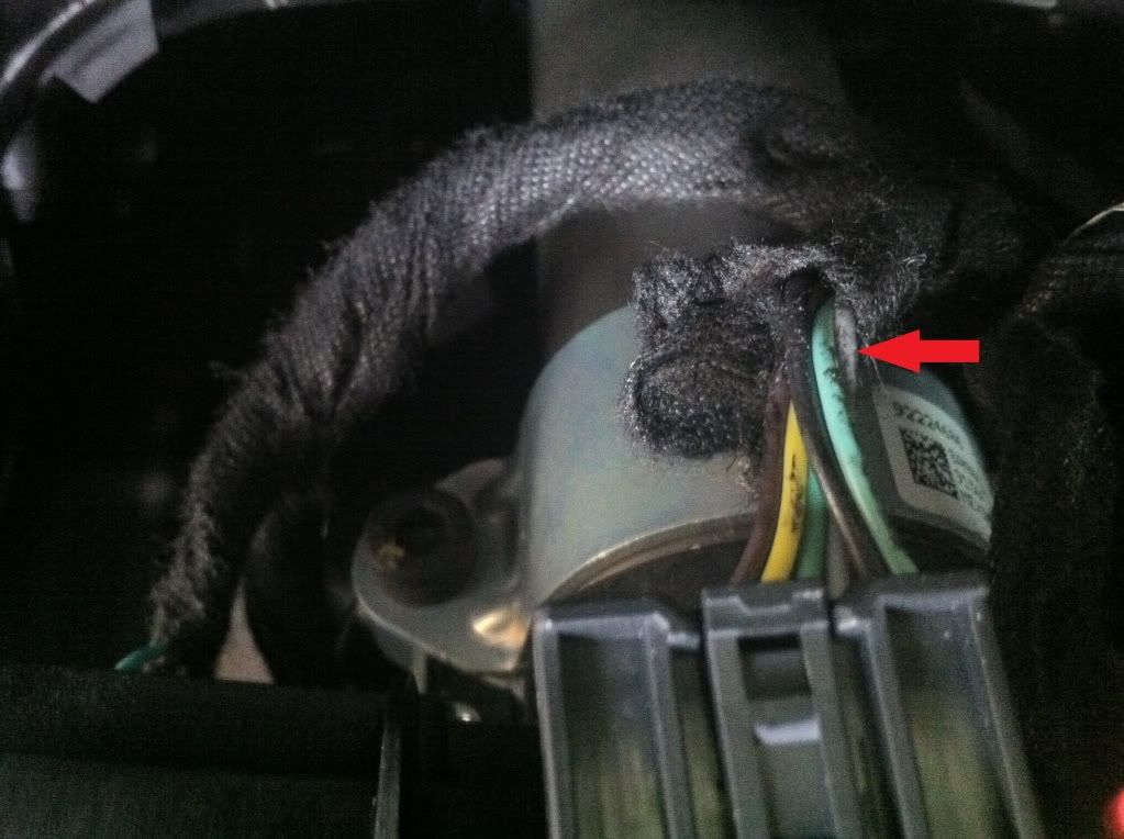
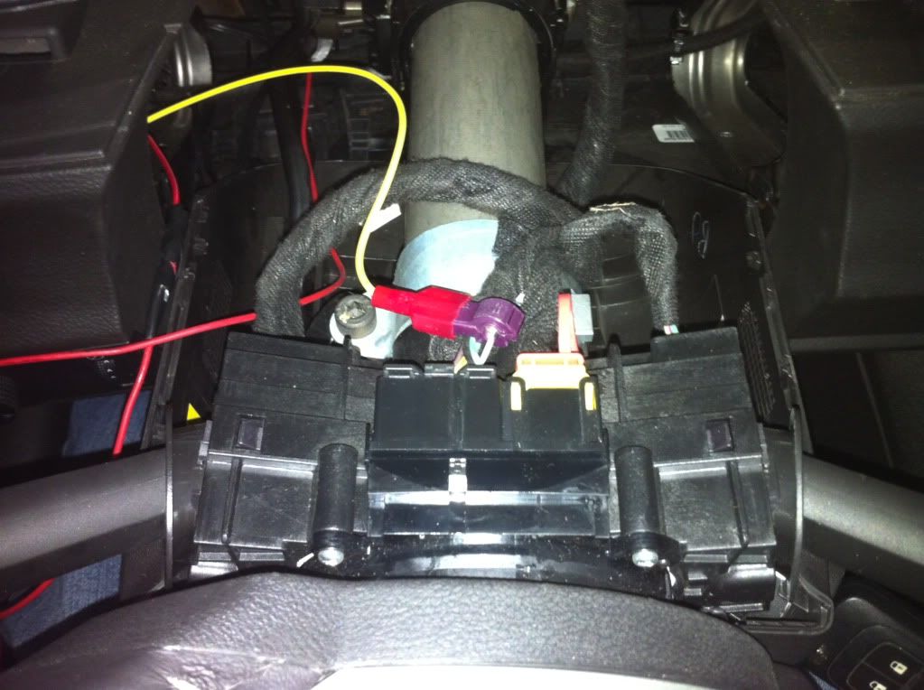
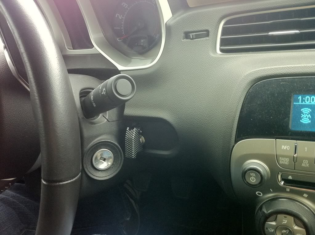
I installed this mod today. Thanks for the awesome DIY write-ups! I combined mwt18's circuit and Eric's Master Switch location and tie-in points. It seems to be working fine. (I especially love the incognito aspect of having the switch in the air duct!)

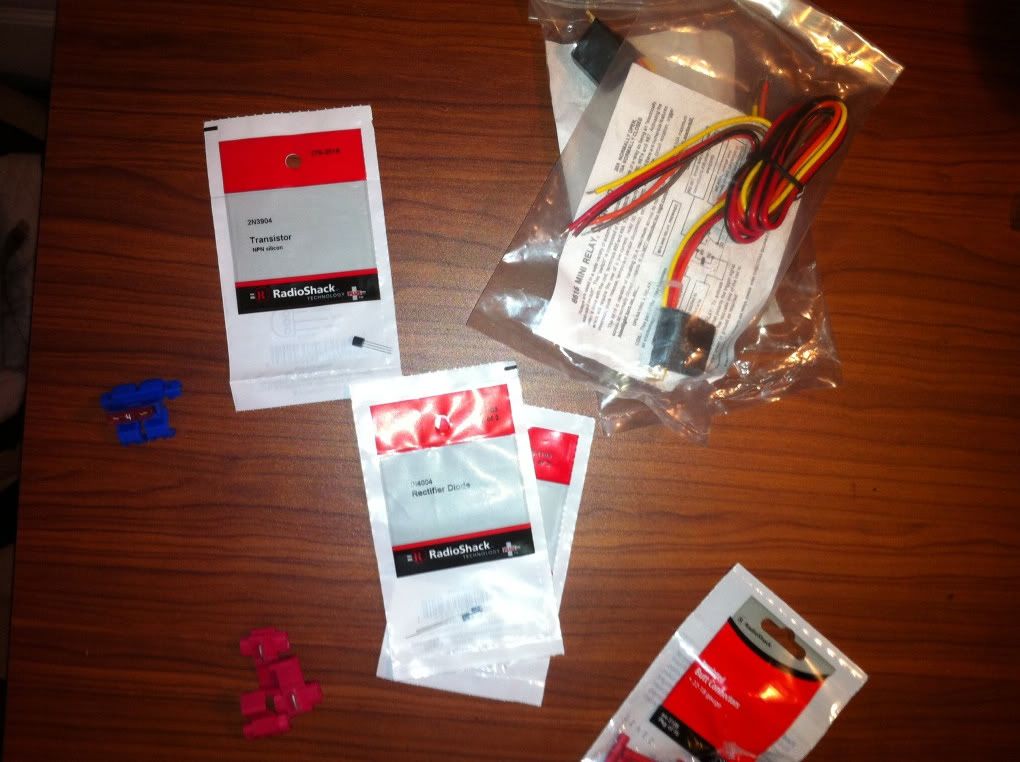
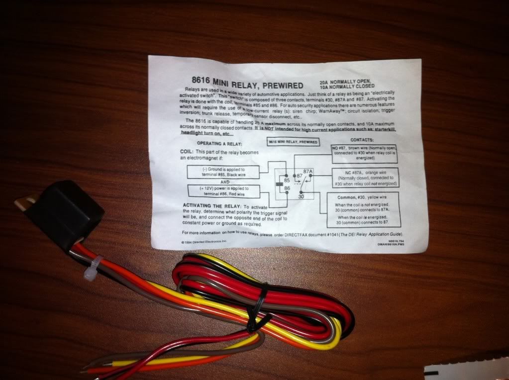
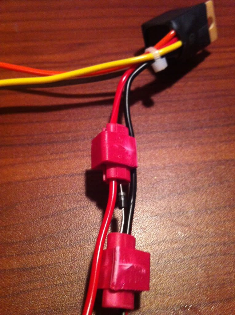
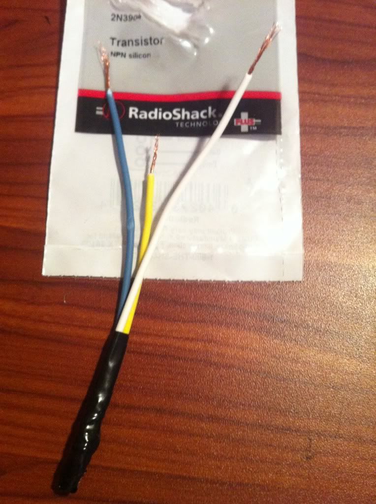
For those of you who are afraid of it, if you're logical and take your time (a LONG time), you can figure it out. Before this install, I had never made a circuit, read a wiring diagram, or installed custom wiring more advanced than an after-market radio in a car before. But it came out alright!

Just a few things for anyone else trying this:
a) The 'parts list' by mwt18 is incomplete. You'll probably want to buy a 3-pack of wire taps. mwt18 uses them in the photo where he taps into the gray wire on the steering column. And they can be used to tie into the green wire from the driver's side fuse box.
b) Please note that the description says the Cruise Control CANCEL button. I spent over an hour with a volt-meter trying to find what was wrong because I expected it work using the Cruise Control button, not the Cancel. :(
c) Other threads discuss it, but this one does not: the line-lock messes w/ your stabilitrac. If you get an error message regarding it, and the three traction-control/stabilitrac icons light up on the tach, it's probably not your installation. It should clear up after a restart or two (no one seems exactly sure on when it will clear).
d) I found it nigh-impossible to get the driver-side fuse box to come out like Eric did. I gave up and used a different approach.
__________________
Three of Swords is offline   Reply With Quote
Old 10-06-2012, 04:18 PM   #33
Coyotekiller
Account Suspended
 
Drives: 2012 AGM 2SS
Join Date: Feb 2012
Location: Beaufort, NC
Posts: 1,383
Subscribed. Hopefully I will be installing one soon.
Coyotekiller is offline   Reply With Quote
Old 10-06-2012, 04:40 PM   #34
jeepguy_1980

 
jeepguy_1980's Avatar
 
Drives: 2010 Camaro 1SS
Join Date: May 2010
Location: Newport News
Posts: 1,310
Quote:
Originally Posted by franknbeans View Post
could this concept work for exhaust cutouts too?
I have a power window panel from a convertible that I thought would be good to use for my cutouts. But I've never made it past the good idea stage.
jeepguy_1980 is offline   Reply With Quote
Old 10-07-2012, 10:12 PM   #35
2011*Camaro*SS
 
2011*Camaro*SS's Avatar
 
Drives: 2011 Camaro 2SS/RS Vert
Join Date: Jul 2011
Location: Lubbock Texas
Posts: 421
any videos of them completed???
__________________
2011*Camaro*SS is offline   Reply With Quote
Old 08-05-2013, 10:12 AM   #36
DarkCry956

 
DarkCry956's Avatar
 
Drives: 2011 Camaro 2SS/RS
Join Date: Oct 2011
Location: Texas RGV
Posts: 794
Will this or something similar work but using the paddle shifts as a momentary switch? Im trying to get a transbrake working on the left paddle. Maybe even a line lock on the right to put a use to it.
DarkCry956 is offline   Reply With Quote
Old 08-16-2013, 06:43 AM   #37
SixGracing

 
SixGracing's Avatar
 
Drives: 2010 2SS/RS LS3 A6
Join Date: Mar 2011
Location: West Haven, UT
Posts: 790
Great job by PASLAG and the others who have contributed to this. I will be building this as well and installing for my line lock. Very nice job. I made the diagram a little cleaner if any of you are interested in printing it for reference. Thanks again!!

Name:  Cruise control Circuit for Line Lock or NOS.jpg
Views: 5042
Size:  59.8 KB
__________________
SixGracing is offline   Reply With Quote
Old 08-18-2013, 09:24 AM   #38
SixGracing

 
SixGracing's Avatar
 
Drives: 2010 2SS/RS LS3 A6
Join Date: Mar 2011
Location: West Haven, UT
Posts: 790
Quote:
Originally Posted by mwt18 View Post
I can't resist helping out my fellow car guys, so here goes...

The parts you need are:
2x Directed Electronics (DEI) 8616 relays (got mine on amazon)
3x 1N4004 diodes (radioshack has 'em)
1x 2N3904 transistor (also stocked at radioshack)
1x in-line fuse (4A)
1x switch (your choice.. just no momentary switches.. the cruise cancel button is your momentary switch!)
~10 ft. of 18 gauge wire (exactly how much depends on where you locate your switch)
1 pack of wire taps (18-22 ga)
1 pack of butt connectors (18-22ga)
1 pack of ring terminals (18-22 ga)

Here's a pic of the components:


Close up of the prewired relay with wire color code:

The orange wires are not used in this application, so just cut them off and tape the ends.

My soldering skills are horrible, so I used wire taps to place the diodes across the relays and then wrapped it up with tape. Here's a pic before taping it up:


Next, is the transistor. The little bugger has 3 pins on it (C,B, and E) and they aren't all that flexible and break easily so take your time and carefully solder or otherwise connect them to some lead wires (different colors on the lead wire helps identify which pin is which). Then wrap it up in tape to secure. Here's that pic:


Now you're ready to build the circuit...Print out the diagram in my earlier post and label the different color wires on the print out. Then just use butt connectors and wire taps to join.. Here's mine:


In the end, you'll have 4 exiting wires:
  • Yellow from one of the relays -- This goes to the gray wire in the steering column.
  • Brown from the other relay -- This goes to the solenoid.
  • Red wire -- To Arm switch and ultimately 12V source.
  • Black wire -- To ground.

Next, I took the whole thing and wrapped it up in tape. I left one of the mounting holes on the relay open on one end and the 4 wires exit on the other end. This is a pretty good spot to mount it in the car (driver's side fuse panel):


The above pic also shows where you can ground the circuit (put ring terminal on end of black wire and attach to screw as shown)

Now, run the yellow wire up to the steering column and tap into the gray wire shown here:


Once you're tapped in, it will look something like this:


The brown wire needs to pass through the firewall and connect to the solenoid. There is a hole in the firewall that is perfect for this.. For the location, see this thread.

Now, is where things become dependent on where you locate the switch..

All's left to do is run the red wire to the switch and then to 12V..
A good place to tap into 12V is the BCM (it's above the accelerator pedal). There are 3 red/white wires that go into the white plug (farthest plug from front of the car). Run red wire here... Don't forget to add the fuse!
Will add pic..

This is where I put my switch... If you have a HUD, you'll obviously need to find another spot..


I'll finish this up when I get some more time...
Awesome! Thanks for the pic tutorial. I think the only other thing you could have done to make this a bit cleaner would be using heat shrink tubing instead of electrical tape. Plus tape comes undone over time. Otherwise, incredible write up. Thank you!
__________________
SixGracing is offline   Reply With Quote
Old 08-18-2013, 09:28 AM   #39
SixGracing

 
SixGracing's Avatar
 
Drives: 2010 2SS/RS LS3 A6
Join Date: Mar 2011
Location: West Haven, UT
Posts: 790
One more thing. I'm having a PCB built with Surface mount parts, encased and complete with a d connector and pigtail. So all you'd need to do is mount the circuit board, attach the pigtail to the cars components (Ground, Gray Cruise wire, Solenoid, and 12V) and plug the pigtail into the connector. Done! I'll update. I can have them built cheap if anyone is interested. Plus i'm looking at other applications and switches in the car where something like this can be done in other places. Like the tap shift buttons, T/C button etc.. Stay tuned.
__________________
SixGracing is offline   Reply With Quote
Old 08-18-2013, 11:14 AM   #40
Gayton81
 
Gayton81's Avatar
 
Drives: 2012 2SSRS
Join Date: Jul 2013
Location: Huntsville, AL
Posts: 171
Quote:
Originally Posted by SixGracing View Post
One more thing. I'm having a PCB built with Surface mount parts, encased and complete with a d connector and pigtail. So all you'd need to do is mount the circuit board, attach the pigtail to the cars components (Ground, Gray Cruise wire, Solenoid, and 12V) and plug the pigtail into the connector. Done! I'll update. I can have them built cheap if anyone is interested. Plus i'm looking at other applications and switches in the car where something like this can be done in other places. Like the tap shift buttons, T/C button etc.. Stay tuned.
PM me when you have a price for one, I am highly interested!
Gayton81 is offline   Reply With Quote
Old 08-18-2013, 02:19 PM   #41
DarkCry956

 
DarkCry956's Avatar
 
Drives: 2011 Camaro 2SS/RS
Join Date: Oct 2011
Location: Texas RGV
Posts: 794
PM me I'm interested as well. Specially if it works on the paddle shifters

Quote:
Originally Posted by SixGracing View Post
One more thing. I'm having a PCB built with Surface mount parts, encased and complete with a d connector and pigtail. So all you'd need to do is mount the circuit board, attach the pigtail to the cars components (Ground, Gray Cruise wire, Solenoid, and 12V) and plug the pigtail into the connector. Done! I'll update. I can have them built cheap if anyone is interested. Plus i'm looking at other applications and switches in the car where something like this can be done in other places. Like the tap shift buttons, T/C button etc.. Stay tuned.
DarkCry956 is offline   Reply With Quote
Old 08-18-2013, 02:48 PM   #42
Rcfiddy1
Sold car...
 
Rcfiddy1's Avatar
 
Drives: 2010 Rally Yellow 2SS/RS #37115
Join Date: Oct 2009
Location: Manalapan, New Jersey
Posts: 2,019
IM interested also...
__________________
Build Thread
ECS Novi 1500 Supercharged, LS3 conversion, Small blower cam, Alky Meth injection, 3:45 rear, BMR Suspension parts, 1LE Sways, Billy Boat ZL1 dual mode exhaust.
Rcfiddy1 is offline   Reply With Quote
 
Reply


Posting Rules
You may not post new threads
You may not post replies
You may not post attachments
You may not edit your posts

BB code is On
Smilies are On
[IMG] code is On
HTML code is Off

Forum Jump

Similar Threads
Thread Thread Starter Forum Replies Last Post
Calling all central Texans! Cruise for charity on June 9th!!! Need YOUR help! TAG UR IT USA - Texas 71 06-11-2010 02:10 AM
Coastal Cruise Inzanesrt4 USA - Northwest / Pacific Northwest 6 06-08-2010 03:47 PM
Circuit Motorsports Daytona Beach / Central FL Cruise Circuit Motorsports USA - Southeast 9 09-26-2009 09:42 AM
Marks Cruise Night Connecticut Closing Event 9/14 irocnroll USA - NY / NJ / PA 21 09-19-2009 11:04 AM
Woodward Dream Cruise - F-Body Cruise/Parking on Saturday August 15th 2009 SlpDave USA - Great Lakes 11 08-19-2009 04:26 PM


All times are GMT -5. The time now is 01:42 PM.


Powered by vBulletin® Version 3.8.9 Beta 4
Copyright ©2000 - 2024, vBulletin Solutions, Inc.