You are browsing camaro5 

|
 03-24-2013, 11:19 AM
|
#43 |
         
Drives: 2011 RJT 2LT/RS Convertible Join Date: Nov 2009
Location: Western Massachusetts
Posts: 3,381
|
Does anyone have a pic of the 1LE separator and its install ?
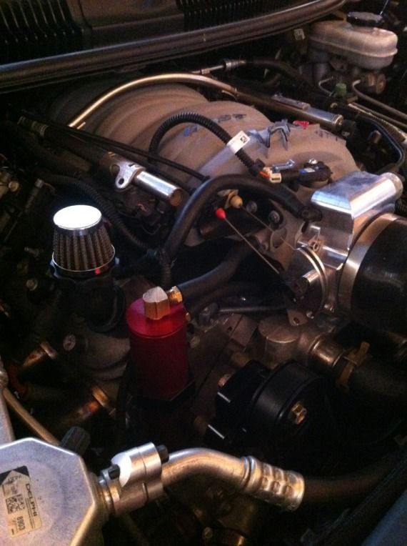
I ended up going with the Saikou Michi can for three reasons. The reliability of the check valves in the RX don't seem to be really great. I like the screw off bottom of the elite but it doesn't have a tube baffle input only the metal mesh baffle. Each saikou can is custom built for where ever you want to mount it. I am able to now mount it in a location that the drain can be easily reached. Everything about the can is modifiable ! I know I only said three reasons but the fourth was a welcome surprise, it was cheaper 
__________________
1st IPF Supercharged 2011 2LT/RS RJT Convertible
 |

|

|
|
03-24-2013, 12:57 PM
|
#44 | |

Drives: 2016 2SS coupe 2015 3LT Stingray Join Date: Aug 2012
Location: El paso texas
Posts: 880
|
Quote:
__________________
Ported intake manifold and throttle body kooks 2" headers no cats
|
|
|
|
|
|
03-24-2013, 01:05 PM
|
#45 |
|
Im a noob

|
i was looking at the gm version and i read that it should only be used for the track and never to be used during temps 23F or below,, why is this?
http://sandyblogs.com/techlink/?p=1145#comment-2141 |
|
|
|
|
03-24-2013, 01:31 PM
|
#46 | |
|
Account Suspended
Drives: 2012 Camaro RS, RX supercharged Join Date: Dec 2009
Location: Bradenton, FL
Posts: 6,063
|
Quote:
Here is a breif history from the beginning of the internal combustion engine:  This section does not cite any references or sources. Please help improve this section by adding citations to reliable sources. Unsourced material may be challenged and removed. (April 2012) From the late 19th century through the early 20th, blow-by gases were allowed to find their own way out to the atmosphere past seals and gaskets. It was considered normal for oil to be found both inside and outside an engine, and for oil to drip to the ground in small but constant amounts. This had also been true for steam engines and steam locomotives in the decades before. Even bearing and valve designs generally made little to no provision for keeping oil or waste gases contained. Sealed bearings and valve covers were for special applications only. Gaskets and shaft seals were meant to limit loss of oil, but they were usually not expected to entirely prevent it. On internal combustion engines, the hydrocarbon-rich blow-by gases would diffuse through the oil in the seals and gaskets into the atmosphere. Engines with high amounts of blow-by (e.g., worn out ones, or ones not well built to begin with) would leak profusely via those routes. [edit] Road draft tube The first refinement in crankcase ventilation was the road draft tube, which is a pipe running from a high location contiguous to the crankcase (such as the side of the engine block, or the valve cover on an overhead valve engine) down to an open end facing down and located in the vehicle's slipstream. When the vehicle is moving, airflow across the open end of the tube creates a draft that pulls gases out of the crankcase. The high location of the engine end of the pipe minimises liquid oil loss. An air inlet path to the crankcase, called the breather and often incorporated into the oil filler cap, meant that when a draft was generated at the tube, fresh air swept through the crankcase to clear out the blow-by gases.[1] The road draft tube, though simple, has shortcomings: it does not function when the vehicle is moving too slowly to create a draft, so postal and other slow-moving delivery vehicles tended to suffer rapid buildup of engine sludge due to poor crankcase ventilation. And non-road vehicles such as boats never generated a draft on the tube, no matter how fast they were going.[1] The draft tube discharged the crankcase gases, composed largely of unburnt hydrocarbons, directly into the air. This created pollution as well as objectionable odors.[1] Moreover, the draft tube could become clogged with snow or ice, in which case crankcase pressure would build and cause oil leaks and gasket failure.[2] [edit] Positive crankcase ventilation (PCV) During World War II, however, a different type of crankcase ventilation had to be invented to allow tank engines to operate during deep fording operations, where the normal draft tube ventilator would have allowed water to enter the crankcase and destroy the engine.[3] The PCV system and its control valve were invented to meet this need, but no need for it on automobiles was recognised. In 1952, Professor A. J. Haagen-Smit, of the California Institute of Technology at Pasadena, postulated that unburned hydrocarbons were a primary constituent of smog, and that gasoline powered automobiles were a major source of those hydrocarbons. After some investigation by the GM Research Laboratory (led by Dr. Lloyd L. Withrow), it was discovered in 1958 that the road draft tube was a major source, about half, of the hydrocarbons coming from the automobile. GM's Cadillac Division, which had built many tanks during WWII, recognized that installation of PCV on vehicles could bring the first major reduction in automotive hydrocarbon emissions. After confirming the PCV valves' effectiveness at hydrocarbon reduction, GM offered the PCV solution to the entire U.S. automobile industry, royalty free, through its trade association, the Automobile Manufacturers Association (AMA).[citation needed] The PCV system thus became the first real vehicle emissions control device. Positive crankcase ventilation was first installed on a widespread basis by law on all new 1961-model cars first sold in California. The following year, New York required it. By 1964, most new cars sold in the U.S. were so equipped by voluntary industry action so as not to have to make multiple state-specific versions of vehicles. PCV quickly became standard equipment on all vehicles worldwide because of its benefits not only in emissions reduction but also in engine internal cleanliness and oil lifespan.[1][4] In 1967, several years after its introduction into production, the PCV system became the subject of a U.S. federal grand jury investigation, when it was alleged by some industry critics that the AMA was conspiring to keep several such smog reduction devices on the shelf to delay further smog control. After eighteen months of investigation by U.S. Attorney Samuel Flatow, the grand jury returned a "no-bill" decision, clearing the AMA, but resulting in a "Consent Decree" that all U.S. automobile companies agreed not to work jointly on smog control activities for a period of ten years.[citation needed] In the decades since, legislation and regulation of vehicular emissions has tightened substantially, and the toxic emissions of cars and light trucks have decreased substantially. Today's petrol engines continue to use PCV systems. [edit] Components and details  PCV valve on Ford Taunus V4 engine in a Saab 96, between left valve cover and intermediate flange on intake manifold The PCV valve is only one part of the PCV system, which is essentially a variable and calibrated air leak, whereby the engine returns its crankcase combustion gases. Instead of the gases being vented to the atmosphere, gases are fed back into the intake manifold, to re-enter the combustion chamber as part of a fresh charge of air and fuel. The PCV system is not a classical "vacuum leak". All the air collected by the air cleaner (and metered by the mass flow sensor, on a fuel injected engine) goes through the intake manifold. The PCV system just diverts a small percentage of this air via the breather to the crankcase before allowing it to be drawn back in to the intake tract again. It is an "open system" in that fresh exterior air is continuously used to flush contaminants from the crankcase and into the combustion chamber. The system relies on the fact that, while the engine is running under light load and moderate throttle opening, the intake manifold's air pressure is always less than crankcase air pressure (see manifold vacuum). The lower pressure of the intake manifold draws air towards it, pulling air from the breather through the crankcase (where it dilutes and mixes with combustion gases), through the PCV valve, and into the intake manifold. The PCV system usually consists of the breather tube and the PCV valve. The breather tube connects the crankcase to a clean source of fresh airthe air cleaner body. Usually, clean air from the air cleaner flows into this tube and into the engine after passing through a screen, baffle, or other simple system to arrest a flame front, to prevent a potentially explosive atmosphere within the engine crank case from being ignited from a back-fire in to the intake manifold. The baffle, filter, or screen also traps oil mist, and keeps it inside the engine. Once inside the engine, the air circulates around the interior of the engine, picking up and clearing away combustion byproduct gases, including a large amount of water vapor which includes dissolved chemical combustion byproducts, then exits through another simple baffle, screen, or mesh to trap oil droplets before being drawn out through the PCV valve, and into the intake manifold. On some PCV systems, this oil baffling takes place in a discrete replaceable part called the oil separator. During the mid 1960s, substantial work was completed on an entirely independent crankcase ventilation system. The Engine Ventilation System had its own air intake filter, a sizable crankcase gases filter, condensate chamber, and highly engineered air flow valve.[citation needed] The system recycles clean water vapor, filters light oil, and filters air into the intake system before the carburetor, resulting in lower carbon monoxide and hydrocarbon emissions and extended engine oil life. Ford Motor Company made this system a requirement on all its material handling equipment (lift trucks) in 1971. This system was also used extensively on over-the-road diesel trucks and irrigation pumps. The AMA's choice[clarification needed] of catalytic converter made automotive use unlikely.[citation needed] The PCV valve connects the crankcase to the intake manifold from a location more-or-less opposite the breather connection. Typical locations include the opposite valve cover that the breather tube connects to on a V engine. A typical location is the valve cover(s), although some engines place the valve in locations far from the valve cover. The valve is simple, but actually performs a complicated control function. An internal restrictor (generally a cone or ball) is held in "normal" (engine off, zero vacuum) position with a light spring, exposing the full size of the PCV opening to the intake manifold. With the engine running, the tapered end of the cone is drawn towards the opening in the PCV valve by manifold vacuum, restricting the opening proportionate to the level of engine vacuum vs. spring tension. At idle, the intake manifold vacuum is near maximum. It is at this time the least amount of blow by is actually occurring, so the PCV valve provides the largest amount of (but not complete) restriction. As engine load increases, vacuum on the valve decreases proportionally and blow by increases proportionally. With a lower level of vacuum, the spring returns the cone to the "open" position to allow more air flow. At full throttle, vacuum is much reduced, down to between 1.5 and 3" Hg. At this point the PCV valve is nearly useless, and most combustion gases escape via the "breather tube" where they are then drawn in to the engine's intake manifold anyway.  Should the intake manifold's pressure be higher than that of the crankcase (which can happen in a turbocharged engine, or under certain conditions, such as an intake backfire), the PCV valve closes to prevent reversal of the exhausted air back into the crankcase again. In many cases PCV valves were only used for a few years, the function being taken over by a port on constant depression carburetors such as the SU. This has no moving parts or diaphragm to jam, block or rip like many PCV valves. It also doesn't have a 'one-way' function but the lack of it was never a problem in intake backfire. It is critical that the parts of the PCV system be kept clean and open, otherwise air flow will be insufficient. A plugged or malfunctioning PCV system will eventually damage an engine. PCV problems are primarily due to neglect or poor maintenance, typically engine oil change intervals that are inadequate for the engine's driving conditions. A poorly-maintained engine's PCV system will eventually become contaminated with sludge, causing serious problems. If the engine's lubricating oil is changed with adequate frequency, the PCV system will remain clear practically for the life of the engine. However, since the valve is operating continuously as one operates the vehicle, it will fail over time. Typical maintenance schedules for gasoline engines include PCV valve replacement whenever the air filter or spark plugs are replaced. The long life of the valve despite the harsh operating environment is due to the trace amount of oil droplets suspended in the air that flows through the valve that keep it lubricated. [edit] Alternatives Not all petrol engines have PCV valves. Engines not subject to emission controls, such as certain off-road engines, retain road draft tubes. Dragsters use a scavenger system and venturi tube in the exhaust to draw out combustion gases and maintain a small amount of vacuum in the crankcase to prevent oil leaks on to the race track. Small gasoline two stroke engines use the crankcase to partially compress incoming air. All blow by in these engines is burned in the regular flow of air and fuel through the engine. Many small four-cycle engines such as lawn mower engines and small gasoline generators, simply use a draft tube connected to the intake, between the air filter and carburetor, to route all blow by back into the intake mixture. The higher operating temperature of these small engines has a side effect of preventing large amounts of water vapor and light hydrocarbons from condensing in the engine oil. 
|
|
|
|
|
|
03-24-2013, 02:13 PM
|
#47 | |
 Drives: pleather and Chiclets Join Date: Mar 2012
Location: a line somwhere
Posts: 4,206
|
Quote:
a catch can installed on the dirty side catches and contains the oil and some of the noxious fumes. i run an rx catch can (which works flawlessley) on dirty side and the gm 1LE seperator on the clean side. took it on track and it works just how i hoped it would. no excess pressure no oil going to my intake. i was looking at options like what litle88 did or running another rx catch can for the clean side. Mr. RX himself said just do the 1LE seperator for clean side...cant beat real car guy advice instead of having me buy another of his fantastic products.
__________________
|
|
|
|
|
|
03-24-2013, 08:37 PM
|
#48 |
|
Drives: 2010 2SS Join Date: Jan 2013
Location: Corpus Christi TX
Posts: 634
|
what i dont understand is whats the difference between catch cans..
-_- |
|
|
|
|
03-24-2013, 09:05 PM
|
#49 | |
|
V8 Lounge member #2

Drives: 2001 Ws6 Join Date: Sep 2009
Location: Burbank,IL
Posts: 6,373
|
Quote:
__________________
2001 ws6, 40k miles, Ls3 416 stroker, short block built by PER the rest by me. LPE Ls3 heads milled to 12-1 comp, FAST 102, NW 102, kooks 2", dual DMH cutouts, Magnaflow C/B, BTR cam + springs. Full UMI suspension.
|
|
|
|
|
|
03-24-2013, 09:11 PM
|
#50 |
|
Drives: 2016 2SS coupe 2015 3LT Stingray Join Date: Aug 2012
Location: El paso texas
Posts: 880
|
Tracy superpost awsome reading I had problems understanding but thanks to your posts on ls1 I got it right thanks again
__________________
Ported intake manifold and throttle body kooks 2" headers no cats
|
|
|
|
|
03-27-2013, 10:37 AM
|
#51 |
|
Account Suspended
Drives: 2012 Camaro RS, RX supercharged Join Date: Dec 2009
Location: Bradenton, FL
Posts: 6,063
|
little, with the Mike Norris can run the lines swapped. Enter through the top so the oil trapped in the coalescing chamber does not pull through. In from crankcase in top on MN can and out the side.
|
|
|
|
|
04-01-2013, 02:42 PM
|
#52 | |
|
V8 Lounge member #2
Drives: 2001 Ws6 Join Date: Sep 2009
Location: Burbank,IL
Posts: 6,373
|
Quote:
Thanks Tracy.
__________________
2001 ws6, 40k miles, Ls3 416 stroker, short block built by PER the rest by me. LPE Ls3 heads milled to 12-1 comp, FAST 102, NW 102, kooks 2", dual DMH cutouts, Magnaflow C/B, BTR cam + springs. Full UMI suspension.
|
|
|
|
|
|
04-01-2013, 03:58 PM
|
#53 |
|
Account Suspended
Drives: 2012 Camaro RS, RX supercharged Join Date: Dec 2009
Location: Bradenton, FL
Posts: 6,063
|
Correct.
Then you need clean filtered makeup air for the flushing. If using a vent out breather it's fine for off road if the engine does not pull to much vacuum, but these engines will pull 18-22" of vacuum at idle and deceleration and thats enough to pull seals in as well as pull oil off the wrist pins and crank journals so we run a vac releif valve set to 14-15" max on the opposite valve cover we pull from to avoid this on that type of application. Here is a good explanation of turbo or centrificul SC applications....and not a single system comes from a manufacturer/vendor that comes with the proper system. All just releif pressure and some with a very inadequate oil seperator: While in normal operating when not in boost, the system uses the intake manifold vacuum to pull in clean filtered air through a breather located in the oil fill cap and pulling out the rear of the drivers side valve cover (you can T the valley cover barb as well if desired) and through the can which traps all detectable oil from the crankcase vapors. Then a second checkvalved line will run from the outlet chamber of the can to the inlet side of the turbo (as close to the inlet wheel as possible, right at the coupler where it attaches to the turbo(s) and this provides evacuation suction when in boost. So, when in non boost operation the primary (-8 AN fittings and lines) checkvalved line is providing evacuation and as soon as the valve detects any positive pressure, it closes and the second valve to the turbo inlet side opens for a smooth transition to that vacuum source and not allowing any boost to pressurize the crankcase. As soon as the primary valve detects vacuum from the IM then it reverts back to the primary evacuation mode. The suction -8 lines have integrated high flow checkvalves in them for big boost, big cube applications and they are positive closing when boost is detected. The center of the can (no valve in) is the can inlet and the crankcase vapors travel app 16 " from inlet to outlet and the oil laden vapors are never moxed with the separated/cleaned vapors (unlike any other can on the market). This will give a constant evacuation flow at all times never allowing damaging combustion byproducts that are part of the blow by all engines have to condense and settle into the oil. The result is the ideal (short of a belt driven vacuum pump system which is the best) way to ensure no oil ingestion to cause detonation, and the crankcase continueously is being evacuated. |
|
|
|
|
04-01-2013, 05:14 PM
|
#54 |

Drives: '11 2SS/RS A6 Join Date: Apr 2011
Location: New Orleans
Posts: 504
|
I have a follow-up catch-can question. On the RX cans, I see you offer a single or dual check-valve option. How do I determine which one to choose?
__________________
Performance Mods:
Kooks 1-7/8 LTs; Calico coated w/HFCs, Solo Mach XL catback w/J-pipes, VMax TB, C.A.I. Intake, JRE Tune, RX Catch-Can |
|
|
|
|
04-01-2013, 06:11 PM
|
#55 | |
|
Drives: 2SS RS Join Date: Mar 2010
Location: MD
Posts: 1,272
|
Quote:
__________________
Livernois 2C cam and tune, LS3 conversion, Roto-Fab intake, Kooks headers, DSS driveshaft and axles, BMR suspension parts, VMax ported throttle body, Whipple blower. (623hp).
|
|
|
|
|
|
04-01-2013, 06:56 PM
|
#56 |
|
Account Suspended
Drives: 2012 Camaro RS, RX supercharged Join Date: Dec 2009
Location: Bradenton, FL
Posts: 6,063
|
Turbo or centri blower dual valve. NA or top mount mild blower single valve.
Here is another good link to study from techs all over the world and DI engines: http://isearch.avg.com/images?s=side...genum=4&snd=pg |
|
|
|
|
|
|
|
 |
| Tags |
| apex catch can, apex motorsports, catch can, elite engineering catch can, rx catch can |
|
|