You are browsing camaro5 

|
 01-20-2011, 02:41 PM
|
#1 |
  
Drives: 2012 Challenger SRT8 Auto Join Date: Sep 2009
Location: Central New Jersey
Posts: 839
|
DIY: LS3 Camshaft Install (a lot of pictures, may take a moment to load)
I decided to do my camshaft install in my garage at home and figured it would be a good opportunity to document it as thoroughly as possible so others wondering about doing the same could do so. I get quite a bit of good information from the community here and I try to give back as often as I can where I feel I am knowledgeable so this is one of those attempts. Even though I have quite a few reputable shops nearby, I enjoy the challenge of doing things myself when I feel they are within my mechanical capabilities. Tuning the car is another story, I will leave that to the professionals.
I may have omitted something during the write-up here so I will continue to update the thread as things are called to my attention. Helpful Resources I will say up front that I am not a mechanic but do consider myself mechanically "inclined" in that I am not afraid to dig into the car having prepared myself for the task at hand. I have also never stayed at a Holiday Inn Select so I have that strike against me before I even got started. I did not undertake this task without researching the whole process online, in books, and by posting questions here in the forum when I needed to so here is a list of most of the resources I utilized throughout the project; - The often cited LS1HowTo 4th Gen cam swap article: http://www.ls1howto.com/index.php?article=23 - The following two books available at Amazon.com or your local Barnes & Noble.  - The following threads I got feedback in here at Camaro5: Valve Cover and Transmission cooling line clips: http://www.camaro5.com/forums/showthread.php?t=121956- Engine Torque Specifications are available in both books mentioned above as well as in the following thread: http://www.camaro5.com/forums/showpo...4&postcount=30 - More torque specs from LS1HowTo: http://www.ls1howto.com/index.php?category=1 - The guys at East Coast Supercharging, namely Chris, Doug, and Mike who have tolerated me via email and on the phone over the past several months as I have contemplated what path I wanted to take with upgrading the car. - Last but not least my father, a mechanic for over 45 years who still bleeds Hemi Orange from his MOPAR days of grudge match racing in the 60's, for being there when I needed some pointers and him mentioning things to watch for and especially him resisting the urge to "hold my hand" through the process and just letting me work my way through it as it is really the only way to learn. I'll do my best to mention every tool that was used although I am sure I'll leave out one or two so I will continue to edit the thread as I remember everything, all the consumable items (fluids, gaskets) used as well as the parts that were used so without further babbling here it goes. Parts Used - New 3 bolt camshaft: I used East Coast Supercharging's Big Blower Cam - Double Valve Springs - Titanium Spring Retainers - Spring Seats - Valve Stem Seals - Hardened Pushrods (best to order these AFTER you measure for pushrod length, it takes 10-15 minutes to check) - Comp Cams Rocker Trunion Upgrade Kit Part#13702-KIT (this is optional, available at Jegs or whatever source for Comp Cams stuff) - Katech C5R Timing Chain Part# HME-G68V-2 - 3 bolt camshaft timing gear: GM Part# 12586481 - Front Timing Cover Gasket: GM Part# 12633904 - Front Timing Cover Main Seal: GM Part# 12585673 - two water pump gaskets: GM Part# 12630223 - New crank bolt - M16 bolt longer than the stock one (used to start pressing the harmonic balancer back on the crank snout) with a few washers. Tools Used - Metric shallow and deep sockets in 1/2" and 3/8" ranging from 8mm to 15mm will cover you as well as a 24mm 1/2" for the crank bolt - 3/8" and 1/2" Torque wrenches (up to 250ft/lbs on the 1/2" preferably) - 1/2" breaker bar and some type of pipe to slip over it for leverage (you WILL needs it for the crank bolt) - 10mm flex ratchet wrench - 40 Torx bit - medium sized channel locks - basic straight and philips screwdrivers - 3/8" fuel line disconnect tool (available at any auto parts store) - harmonic balancer puller tool (got the OEM/Chrysler loaner from Autozone) - harmonic balancer installer (if you can't find a longer crank bolt or some M16 threaded rod) - couple of funnels for fluid - fluid pan - two 5/16" wood dowels (available at Home Depot or Lowes and used for keeping the lifters up while swapping the cam) - Comp Cams Hi-Tech Pushrod Length Checker Part# 7702-1 (available at Jegs or again, wherever Comp Cams stuff is) - Valve Spring Compressor tool (I got this one off Ebay for $35, well worth it for me, Ebay Item# 190374215930) - Another Spring Compressor tool option is the one by Crane Cams available at Summit Racing or Jegs. - Hammer (if other tools fail a hammer always works) - Floor jack, jack-stands, ramps, whatever you use to get the front end of the car up off the ground preferably the rear too to keep things level. Fluids, lubricants, gooey stuff - 8 quarts of your favorite motor oil - 2 Gallons of Dex-Cool concentrate (or 3 gallons of the 50/50 premix) - 1 Quart Mobil 1 Syhthetic ATF Transmission Fluid (or whatever your favorite is) - Small tube of Blue (medium) Loctite - Small tube of Red (max strength) Loctitie - Small tube of Perma RTV Hi-Temp Gasket Maker - Small tube of Anti-seize - Assembly lube (this is optional) The Install...... Like I said, I probably left something out but lets get on with it. First a shameless attempt to insert myself and my car into the thread  1. Start by getting the car up off the floor onto jack-stands, ramps, or a lift if available and then disconnect the negative battery cable in the trunk with a 13mm socket, remember to put both windows down a bit before disconnecting or you will get them stuck under the weather stripping and have a hard time opening and closing the doors (don't ask me how I know )2. Open up the radiator to help it breath while draining the coolant out of the system (did I really have to put this, probably not but I make no assumptions about who is reading this) 3. Place something to catch the coolant under the radiator drain plug at the bottom of the driver's side of the radiator. Unscrew the flat tab on the plug about one full turn or so and drain the coolant out of the system. 4. Prepare to remove the stock air intake or aftermarket (I have a RotoFab CAI) intake by undoing the 10mm nut with a deep socket. 5. Unplug the MAF sensor, disconnect the PCV hose from the intake pipe, and remove the intake tube from the throttle body. The stock intake requires a good yank to pop it out, as do some of the aftermarket ones that seat in the stock hole beneath the intake's heat shield. 6. Basically unbolt or disconnect everything you see here in the picture. I chose to unbolt the radiator fans from the radiator just to make removing them out of the engine bay a little easier doing them one at a time. 7. Once all the stuff on top of the radiator is disconnected, tilt it forward and unbolt the two bolts that hold the A/C condenser to the radiator as there is no need to take the condenser out as there is enough play in its lines to prop it up out of the way when swapping the cam out and in. 8. At the bottom of the radiator on the engine side, disconnect the two transmission cooling lines by removing the black plastic cover on the radiator end of the line and popping off the small clip holding the line in with any small pick-like tool (I think I used the smallest allen key I had lying around) and then pulling the lines out of the radiator as well as their holding brackets so they swing freely. You'll want a drip pan underneath them to catch any transmission fluid that comes out of the lines and the radiator. There is also the lower radiator hose that connects to the Water Pump inlet housing which isn't pictured, it was a pain to try and get the hose off so I just unbolted the inlet housing to disconnect it and took the thermostat out. You can go ahead and remove the radiator fans at this point and then the radiator (I did them separate just to make things a little easier working each one out on their own) 9. These are what the two clips look like (if you haven't gotten them out yet to see them yourself). 10. Unbolt the four A/C line brackets with a 10mm socket as depicted in the picture below, one is off to the right (driver's side) that can't be seen in the picture but just follow the line up to the right and you'll come across it. After loosening the line, tuck the transmission cooling lines behind it (engine side) so they don't get snagged on it when you are lifting the condenser out of the way later. 11. Using a breaker bar or any ratchet and a 15mm socket, "tighten" the main belt tensioner to compress it and the main belt will droop off the water pump pulley so you can slip it off. Hang the belt somewhere as it will be reused. 12. If you haven't done so already, and this is the first I am mentioning it, you may want to remove the spark plugs as cranking the engine with them in is a bit of a pain as you'll be fighting each cylinder as it compresses the air inside it when you are cranking it over. Removing the spark plugs wires is a good idea as well to get them out of the way now too. To get the A/C belt off, with the car in neutral (remember this is an LS3 install), crank the engine over counter-clockwise with a 24mm socket on the crank bolt while at the same time using a smooth ratchet handle or something similar to apply pressure against the engine side of the upper belt and walking it off the A/C compressor pulley. IT DOES NOT HAVE TO BE CUT OFF and it can be reused if you use this method as opposed to prying the life out of it with a pry bar 13. With the belts out of the way, go ahead and remove the two eater core hoses from the passenger side of the water pump (have a rag handy to catch any coolant that spills out) and then drape them up out of the way (I put mine up over the piston that supports the hood), and on the driver's side, if you didn't do it earlier, remove the main upper radiator hose, even once the clip is slid back I still had to use some channel locks to break it free from the water pump by twisting it side to side until it broke free. At this point you can also remove the water pump from the front of the engine by unbolting its six mounting bolts with a 10mm socket. It is a good idea to have some cardboard and/or drip pans underneath the car as coolant will be spilling out of the water pump and the block when it is pulled off. 14. In preparation for taking the front timing cover off a few steps from now, loosen the nut on the alternator as shown below as well as remove the two bolts, all are 15mm. Once the nut is loosened and the bolts backed out you'll be able to swing the alternator down and toward the driver's side to gain access to the side timing cover bolts later on. 15. Now the real fun begins, grab your 24mm 1/2" socket, a short socket extension, your 1/2" breaker bar, and whatever pipe you have to slip over the breaker bar for some leverage. Put the car in 4th gear and make sure the E-brake is on good. Go ahead and remove the crank bolt, and yes at some point you will think you are going to break something on the car and just then the crank bolt will start to creak a bit and start to loosen a little at a time. Just make sure the socket is seated good on the bolt as the last thing you want is it slipping off when you are pulling as hard as you can. 16. With the crank bolt out and hopefully nothing broken, get out your harmonic balancer puller tool (I used the OEM/Chrysler one that AutoZone loans out). Leave the car in gear with the E-brake on. 17. This particular puller has a couple of rods of different lengths that are supposed to extend into the crank snout but even the longer of the two was too short for the LS3. 18. Instead I put the stock crank bolt back in but did not thread it in all the way and then used the puller tool with just its threaded bolt pushing against the crank bolt to get the balance as far off as I could. 19. When the puller bolt was threaded as far as it would go I just used a 24mm deep socket (a 7/8" deep socket will work as well) set on the crank bolt which I threaded out some more to press the puller bolt against until the balancer was off the crank snout. I admit this was a bit of a convoluted method and it may have been easier with the bigger claw-like puller tools or one of the Comp Cams tools out there but it worked for me. 20. With the harmonic balancer off, it is time to take the front timing cover off. I went ahead and removed the camshaft sensor by unplugging it at the bottom and then disconnecting the bracket's two 10mm bolts. I later realized you don't have to take the bracket off and really just need to unplug the sensor at the bottom. It was nice to have it out of the way later on when trying to knock the front main seal out of the timing cover. Also at this time, remove the two timing cover bolts that come up from underneath the oil pan with a 10mm wrench (or flex ratchet which makes it a whole lot easier) and then the eight 10mm bolts on the front of the timing cover and pull the timing cover off (it may take a little bit of a tug to break free from the gasket) and removed the gasket as well. You can reuse the gasket if you wish but I chose to replace it with a new one anyway. 21. The negative battery cable runs under the front edge of the oil pan and sits in a kind of tray, this tray has to be disconnected from the oil pan and the block to drop it out of the way and make room for the oil pan to be dropped in a later step. There is a single 10mm bolt on the passenger side and a 10mm nut that holds an A/C line bracket in place and then a 10mm bolt behind it on the front driver's side of the oil pan. Once both sides are disconnected you can rotate the A/C line bracket forward to get the lines out of the way and the cable tray will be free to be moved around a bit when dealing with the oil pan later. 22. In preparation to remove the oil pump, remove its four bolts with a 10mm socket (notice a trend with 10mm bolts, I shoulda bought stock in whoever makes them for GM )23. As mentioned earlier, in preparation for dropping the oil pan, rotate/twist the A/C line bracket forward to get the rear one to kinda fold over the front one and get out of the way. 24. At this point you can drop the oil pan by loosening all of its bolts and get about a 1/2"-3/4" drop out of it which will give you enough room to get in under the oil pump and get to the oil pickup tube bolt. Taking pictures under the car to show all the bolts was too difficult to represent each one that had to be undone so I just did a video instead. 25. With the oil pan dropped there is a bit more room to get to the pickup tube bolt, I stuffed a bunch of shop towels in under the oil pump to help avoid and fishing expeditions into the oil pan if I dropped the bolt. Once the bolt is out the oil pump doesn't come straight off as you have to work it away from the pickup tube by rotating it counter-clockwise while pulling it off the crankshaft. Take note if the pickup tube O-ring is on the tube or not, if it isn't and is up in the oil pump, take it out of the pump and seat it on the pickup tube because if you don't, you run the risk of pinching it or cutting it later on when you reinstall the oil pump and you won't know until you fire the car up and are wondering where your oil pressure is. The second picture below shows the flex ratchet wrench that was a savior when getting the pickup tube bolt out. 26. Before tearing things down anymore, take the car out of gear and rotate the crank over by putting the old crank bolt back in and turning it over with a ratchet until the crankshaft timing gear dot is at the 12 o'clock position and the camshaft gear timing dot is at the 6 o'clock position and then put the car back in gear and don't bother the crankshaft until after the new cam is in. 27. Using a 24mm socket, remove the stock single cam bolt and then squeeze the timing chain against the outside metal bracket of the timing chain tensioner so that you can fit any small paperclip-like thing in the tensioner's retainer hole (I used the smallest allen key I had lying around) as this will relieve the tension on the chain allowing the timing gear to be removed. 28. Remove the two 10mm timing chain tensioner bolts and then pull the camshaft timing gear off the camshaft taking the chain along with it, you may need to use something to LIGHTLY pry the gear off leveraging against the block but be sure to put a rag against the block as it is aluminum and can easily be scored if you pry too hard. Just a tiny bit altering side to side will get it loose enough to pull off by hand. 29. This is the full view of the LS3 timing chain tensioner and has what I came to find out two schools of thought surrounding its use in a cam upgrade when using and upgraded timing chain and a 3 bolt camshaft hence a 3 bolt camshaft timing gear. Here is one of my threads (happened to be a thread about dropping the oil pan) where the tensioner discussion occurred among many others that are out there; http://www.camaro5.com/forums/showthread.php?t=122560. I decided to stay with the LS3 tensioner based on my own research and knowing that I have to live with decision. Other folks have gone back to the old style LS2 block based on their own experiences so each method probably has its merits. The theory is that the tensioner was not meant to be used with a 3 bolt timing gear or stiffer aftermarket chain and is prone to breaking and dropping bits of plastic and/or metal into the oil pan. This is opposed to the theory that even though that may happen a VERY VERY small percentage of the time (a half dozen or so instances I could find among thousands upon thousands of the tensioners that are out there in LS3's in the Camaros and the Vettes for a few years now) the tensioner saves a lot more broken timing chains compared to the old ls2 style block once the chain starts to stretch. Either way, I strongly suggest you read up on the tensioner vs block subject and decide for yourself which way to go. 30. With the timing gear out of the way, remove the camshaft retainer plate by unbolting the four recessed bolts with a 40 Torx bit and keeping a hand on the retainer plate when the last bolt comes out as it may fall. 31. Now it is time to move up top to start working into the valvetrain before we can actually remove the stock cam. Start by removing the fuel line retainer clip with a screwdriver on the rear driver's side of the intake manifold. 32. Before disconnecting the fuel line it is a good idea to open the gas cap to relieve any pressure in the system (not sure if this actually makes a difference but it sounds good ), then, using a 3/8" fuel line disconnect tool pop the fuel line off (it takes a pretty good tug to get it to pop off) and make sure you have a rag underneath to catch any fuel that spills out.33. Unbolt the fuel line retainer bracket from the passenger side of the intake manifold with a 10mm deep socket and unclip the fuel line from both driver and passenger sides. 34. Hang the fuel line up out of the way once it is disconnected from the driver side, there is no need to disconnect the passenger side. 35. On the driver side of the engine, disconnect the main coil plug and unbolt the five coil harness bolts with a 10mm deep socket and then remove the entire coil harness/bracket/whatever from the valve cover. 36. Remove/loosen the four 8mm valve cover bolts and remove the valve cover. 37. Remove all eight driver side rockers with an 8mm socket as well as the rocker pedestal bracket/seat, and finally all the pushrods. 38. On the passenger side next to the throttle body, disconnect the fuel breather tube (I think that is what it is) and the plug next to it (no idea what it is) as well as the two clips on the breather tube and then hang the tube up out of the way the same way the fuel line was earlier. 39. Disconnect the passenger side main coil plug, pop off the two wire bundle holders up off the coil harness bolts, unbolt the five coil harness bolts with a 10mm deep socket, and then finally remove the harness from the valve cover. 40. Remove/loosen the four 8mm valve cover bolts and then work the valve cover out from under the wire bundles while also paying attention to the PCV tube coming out from under everything as well. 41. Remove all the passenger side rockers with an 8mm socket, the rocker pedestal bracket/seat, and all the pushrods. 42. Thread the stock camshaft bolt about halfway back into the camshaft, rotate the camshaft by hand several times to get the lifters up and then insert your two 24" long 5/16" wood dowels into the oil journals on both sides of the camshaft to make sure the lifters don't drop when you pull the camshaft out. 43. At this point you can start to work the camshaft out slowly by pulling on the stock bolt and rotating the camshaft a bit to help it along and using the camshaft bolt to get some leverage to keep the back end of the camshaft from dropping down and dragging its lobes over the bearings on the way out. Stop when you get the first quarter of the camshaft out so you can move the A/C condenser up out of the way to get the rest of cam out. 44. With the A/C line brackets unbolted from an earlier step, there is enough slack in the lines to work the condenser passenger side up out of the engine bay and then laying it on top of the throttle body (protecting the throttle body with a few rags before doing so). Tie off the condenser to the hood hinge with some rope or a bungee-cord. 45. Finish working the stock camshaft out of the block making sure to fully support it all the way out and trying not to drag it out, rotating it by hand a few times if it seems to get stuck. Get the new camshaft ready by threading three of the 10mm water pump bolts into the cam (which will help with leverage in getting the last quarter into the block). At this point you can either use engine assembly lube or motor oil (I just used the Mobil 1 5W-30 I use in the car) and lube the first quarter of the new cam and then start installing it, rotating as you go and adding oil to every quarter as you install it into the block. If the cam gets stuck, do not force it, ease back a bit, rotate it, then try again, using the water pump bolts to lever the back end of the cam up to get it up into the bearings. 46. When the camshaft is completely in, rotate it by hand several times to ensure it spins somewhat freely, remove the 5/16" dowels, two of the water pump bolts, and then drop the A/C condenser back down into the engine bay. 47. Clean off the back side of the camshaft retainer plate and then lightly oil the built-in gasket as well as the surface that sits flush against the camshaft face. 48. Reinstall the retainer plate by putting some blue Loctite on its four bolts and then torque them down to 11ft/lbs with a 40 Torx bit. Do not over tighten the recessed bolts or you risk cracking the retainer plate. Use the one water pump bolt to pull the camshaft flush against the plate and make sure it still rotates freely by hands (it won't spin freely but you should be able to turn it with a little effort by hand). Remove the water pump bolt once verifying the cam doesn't get hung up on anything while rotating. 49. Reinstall the timing chain tensioner (or the ls2 style block if you chose to go that route) making sure the spring is still being held by the retainer clip. Put a little blue Loctite on the two 10mm tensioner bolts and then torque them down to 22ft/lbs. 50. After having dipped the new timing chain in oil drape it over the new 3-bolt timing gear, apply a little oil to the face of the camshaft, rotate the camshaft so that the pin on its face that inserts into the timing gear is at the 3 o'clock position, set the timing chain up under the crankshaft onto its timing gear in such a way that the camshaft timing gear timing mark is at the 6 o'clock position (crankshaft timing mark should still be at 12 o'clock position) and then use a water pump bolt through the cam gear and thread it a little into the camshaft in the corresponding hole to help guide the gear onto the front of the camshaft, pulling on the bolt to prevent the cam from getting pushed back into the block while pressing the timing gear onto it. 51. Use some blue Loctitie on the 3 cam bolts then hand tighten all three down using a 13mm socket, snugging each one up with a ratchet, then one the final pass torque each one down to 26ft/lbs. Squeeze the timing chain against the metal portion of the tensioner (I used a little shop towel against the chain to protect its surface, call it paranoia) and then pull whatever you have in the tensioner retainer hole out so the tensioner presses against the chain and takes the slack out of it. 52. Reinstall the oil pump, it is a little bit tricky getting it back on the crankshaft grooves and onto the pickup tube at the same time, you have to start it out a little counter-clockwise from its installed position, angle it back onto the pickup tube, then push it back and rotate clockwise to its final position. Probably a poor explanation but you'll see what you're up against, it just takes patience and resist trying to force it. Once you get the pump back on put a little blue Loctite on its four 10mm bolts and thread them back in but not all the way, just so they barely hold the pump against the block. Crank the engine over several times by hand with the old crank bolt installed and a 24mm socket as this will allow the oil pump to center itself on the crank. Finally torque the four bolts down to 18ft/lbs. Now you can have fun reinstalling the pickup tube bolt, stuff some rags in the oil pan as a precaution, put a little blue Loctite on the 10mm bolt and thread it in as far as you can with your fingers. Finish the bolt off by tightening it down fairly snug, it calls for 9ft/lbs but you won't be fitting a torque wrench in there. Make it snug and then add a 1/4 turn, that along with the Loctite should keep it in place. 53. This is also a good time to button up the oil pan, all the 10mm oil pan bolts torqued to 18ft/lbs, the rearmost at the very bottom by the bell housing to 9ft/lbs, the 13mm starter bolts to 43ft/lbs, and the two 15mm bell housing bolts to 37ft/lbs. Again, here is the video that shows all the bolts to tighten. 54. Moving back up to the valvetrain, it is a good time to check for pushrod length with an adjustable pushrod length checker. Regardless what someone tells you your pushrod length "should" be with a new cam it only takes a short time to measure it yourself and be sure you are using the right lengths. I used the Comp Cams 7702-1 checker which has a base length of 6.8" and extends all the way out to 7.8" with each turn of the tip representing 50/1000th of an inch. I measured the stock pushrods to be 7.375" and with the new cam having a slightly smaller base circle than the stock cam I knew I was going to need a slightly longer pushrod but not exactly how much until I measured it. 55. The methods I used for checking pushrod length were to find the pushrod length with a rocker torqued down and at zero lash then adding my targeted lifter preload to the length checker and verifying its length by bolting the rocker just down to zero lash and then getting 1.5 turns out of the rocker pedestal bolt to get to 22ft/lbs. Some things are better explained by watching them so here is a video of the entire process I went through to measure and then verify the pushrod length I was going to use. So after all my measurements I came up with a 7.325" base pushrod length, added 0.075" preload (GM spec on the stock lifters is 0.060" so I erred slightly on the high side of spec) and came up with a 7.4" pushrod which makes sense as the new cam's base circle was about 0.033" smaller than the stock intake cam lobes and 0.055 smaller than the stock exhaust cam lobes (base circles on the stock cam are different for intake and exhaust yet all the stock pushrods were the same length so the exhaust lifters were carrying about 0.020" more preload than the intake lifters). I picked up some Comp Cams Hi-Tech 5/16" diameter 7.400" length hardened pushrods after having determined the proper length I needed. 56. With the pushrod lengths determined it is time to move onto swapping out the valve springs. I went with Manley Dual springs and Titanium Retainers, their spring seats and valve stem seals. 57. Now the process of swapping out the valve springs and their supporting hardware. There are two primary ways to ensure that the valves don't fall into the cylinder when swapping the springs. The first is to use a compression test kit that threads into the spark plug hole and then into a compressor to make sure the valves stay up when you remove the locks but more so when the valve stem seals are removed. AutoZone loans such a tool out, you just have to remove the schrader valve pin before threading the plug into the spark plug hole. I just wanted to mention that I tried this method and it is a real pain to thread the hose into the spark plug hole, and that was on the front of the engine so if you are more patient and have smaller fingers I say go for it. One caution I will throw out there is if you are holding the valves up with air pressure and the valve you are changing the spring on should get compressed down enough to break the seal in the cylinder and the locks are off the valve stem, there is a slight risk the valve will fall down in the cylinder, a.k.a. have fun taking the head off to retrieve it.  The second method and the one I used is the "Top Dead Center" method where you start out with the crankshaft timing gear mark at the 12 o'clock position and the camshaft timing gear dot at the 6 o'clock position which puts both cylinder 1 and 6 at top dead center. When you rotate the crank by hand 90 degrees clockwise from that starting position it will put pistons 8 and 5 at TDC (crankshaft timing dot at 3 o'clock), another 90 degrees puts 7 and 4 at TDC (crankshaft timing dot at 6 o'clock), the final 90 degrees puts 3 and 2 at TDC (crankshaft timing dot at 9 o'clock). When each pair of pistons is though to be at TDC you can simply verify by poking a small piece of 5/16" wood dowel in the spark plug hole of each respective cylinder and you should bump into the top of the piston and not be able to put the dowel all the way in. If you can, that piston is not at TDC so do not start the springs on that cylinder until it is. (This image is from the popular LS1Howto cam swap post)  58. With the piston at TDC for the cylinder you are working on and a rag placed around the spring to catch any locks that decide to "pop" out, place your spring compressor on the first spring and compress the spring down until the locks come loose (as mentioned earlier I used Ebay Item# 190374215930 and actually had to shave a little bit out of the insides of the tool to have a little more clearance for the locks on the intake springs which are offset from the rocker pedestal bolt). It maybe a good idea to place a large socket on top of the spring retainer and give it a few taps with a hammer so the locks unseat a little bit and come loose when the spring is compressed as opposed to them "popping out" when the valve stops going down when it touches the top of the piston. Remove the locks (if you can't get them with your fingers it is easiest to use a magnet of some sort), uncompress the spring, then remove the retainer and spring. 59. Using a set of channel locks, grab the valve stem seal and spring seat (the stocks ones are both those things in one piece) and with a good grip rotate the seal/seat around the valve stem while pulling up lightly until you feel it break free. Once you remove it, if the valve stem hadn't gone down while compressing the spring earlier, it will probably fall down until it contacts the piston at TDC underneath it which is about a 1/2"-3/4" drop. 60. Drop the new spring seat over top of the valve stem and then drop the valve stem seal a press it flush as far down as you can. You will not be able to press it all the way on by hand so use a 12mm deep socket and tap it on with a hammer, when it is seated all the way you will hear a noticeable change in the hammer's pitch when you're tapping the socket. 61. Drop the new spring on the seat, put the retainer on, get your "catch rag" in place, then use the spring compressor tool to press the spring down so you can get the locks back on making sure to watch the locks seat properly as you are uncompressing the spring. 62. Repeat the process on the other 15 springs and be sure to take your time, especially with cylinders 7 and 8 all the way at the back. You will stretch and twist in ways you didn't think possible, at least I did. To give you an idea of how the process actually looks and how long it takes I did a video of swapping one of the intake springs on cylinder 2, it is 15 minutes long but walks you through the entire process. 63. I decided to upgrade the bearings in the stock rockers with the Comp Cams Trunion Upgrade Kit (Comp Cams Part# 13702-KIT). This is NOT an absolute necessary thing to do as there are literally thousands of LS3's running around with higher lift cams and stiffer springs that what comes stock and I have only seen a few instances where folks have had issues with the stock press-fit needle bearings blowing out. I did the upgrade solely because I feel it is cheap insurance (the kit can be found for $120-$135 online) and I had the valve train ripped apart already so why not. The upgrade is very simple, here are the instructions straight from the Comp Cams site; 13702-KIT Trunion Upgrade Installation Kit I simply sat each rocker on top of a large deep socket and punch the press-fit bearing out with a smaller deep socket and a hammer. The upgraded trunions and bearings went in pretty easy, I just used some a small workbench press and some sockets to press the bearings in. The nice part is everything is secured with a snap ring on both side of the trunion. 64. Once all the springs are swapped, rocker trunions upgraded (if you decide to go that route), and pushrods of the proper length are acquired go ahead and reinstall the entire valvetrain by doing one cylinder at a time while its piston is at the Top Dead Center firing position (intake/exhaust lifters on the base circle of the cam). Each rocker pedestal bolt gets torqued to 22ft/lbs with either an 8mm socket for the stock bolts or a 6mm hex bit for the Trunion upgrade bolts. The following shows how to get each piston at its Top Dead Center firing position so its intake and exhaust rockers can be installed using the timing gear marks/dots on the camshaft and the crankshaft. - Cylinder 1: camshaft dot at 12:00 o'clock/crankshaft dot at 12:00 o'clock - Cylinder 8: camshaft dot at 1:30 o'clock/crankshaft dot at 3:00 o'clock - Cylinder 7: camshaft dot at 3:00 o'clock/crankshaft dot at 6:00 o'clock - Cylinder 2: camshaft dot at 4:30 o'clock/crankshaft dot at 9:00 o'clock - Cylinder 6: camshaft dot at 6:00 o'clock/crankshaft dot at 12:00 o'clock - Cylinder 5: camshaft dot at 7:30 o'clock/crankshaft dot at 3:00 o'clock - Cylinder 4: camshaft dot at 9:00 o'clock/crankshaft dot at 6:00 o'clock - Cylinder 3: camshaft dot at 10:30 o'clock/crankshaft dot at 9:00 o'clock Basically starting at 12 and 12 on the timing gears sets cylinder 1 ready and then in sequence with each clockwise 90 degree turn of the crankshaft you go from cylinder 1 to 8, 7, 2, 6, 5, 4, and finally 3. Once all the rockers are installed, turn the engine over several times by hand and then go back and verify all the rocker pedestal bolts are still torqued to 22ft/lbs. 65. Punch the front main seal out of the timing cover by using a blunt tip punch or a screwdriver, whatever you choose, be careful not to score the inside lip of the timing cover that the seal presses in against. Lightly oil the inside lip of the timing cover and press then sit the seal flush in the opening and press it in evenly until it is fully seated. I was actually able to press the seal in a little bit at a time by using my thumbs and working my way around the seal until it was all the way in. DO NOT OIL THE INSIDE OF THE SEAL, it is meant to mate up with the harmonic balancer DRY when the balancer is installed in a later step. 66. At the front bottom corners of the block where the block, oil pan, and timing cover come together, put a bead of RTV Hi-Temp Sealant on both corners. Scrape off as much of the sealant that was already there from the factory with your fingernail or some type of sharp plastic edge (old credit card worked good for me). You don't want to use anything metal to avoid possibly scoring the aluminum (I may be overly paranoid here  ) )67. Clean the surface of the timing cover where the gasket meets up to and then very lightly oil it with your finger before setting the gasket against it and threading in a few of the timing cover bolts just far enough to hold the gasket in place. 68. After having cleaned off the front face of the block where the timing cover gasket meets up with it and very lightly oiling it, put a little blue Loctite on each of the eight 10mm front timing cover bolts as well as the two that come up from underneath the oil pan. Place the timing cover firmly against the block and pressing it firmly down against the oil pan to get the RTV Sealant worked out of the seam. Thread in all ten timing cover bolts but DON NOT torque them down yet, just thread them far enough in so there is a little side-to-side play in the timing cover if you push it with your fingers. We don't want to torque it down until the Harmonic Balancer is reinstalled and the front main seal/timing cover can find its center around the balancer. After threading the timing cover bolts in you can also reinstall the camshaft sensor bracket with its two 8mm (or 10mm) bolts torqued to 9ft/lbs and the sensor plugged in at the bottom of the bracket. Finally place the Harmonic Balancer back on the crank and seat it as flush and as far as you can by hand, put the car back in gear with the E-brake on. 69. You have a few options to press the balancer back on; - Purchase, borrow, "acquire" a balancer install tool, Comp Cams makes a nice puller/install combo or just an installer - Get a foot long length of M16 threaded rod, a couple of large M16 nuts, and a few appropriately sized washers and make your own installer tool (I couldn't find M16 threaded rod anywhere around where I live, probably just looked in the wrong places) - Get an M16 bolt longer than the stock crank bolt along with a few washers to help get the balancer started and pressed on about halfway before using the old crank bolt to finish it off with. This is the method I used as I had a longer M16 bolt that came with the crank pinning kit (to pin the crank for a future Centri blower) I got from the shop I was getting my parts from. Whatever you do DO NOT use the old crank bolt to try and get the balancer started onto the crankshaft, the bolt probably won't even reach the threads but even if it did reach the first few you run the risk of stripping out the first few threads in the crankshaft. 70. Once the balancer is on about halfway or you feel the longer M16 bolt bottom out, switch to the old stock crank bolt and finish it off by tightening it down as far as you can and then torquing it to 240ft/lbs (have fun with that). Remove the old crank bolt and install the new crank bolt with a little red Loctite on the end before torquing it down to 37ft/bs and then another 140 degrees of rotation (have fun with that too ). I just marked the head of the bolt with a sharpie marker and the face of the balance with the target I had to rotate the bolt to).71. Take the car out of gear and crank the engine over clockwise by hand several times with a 24mm socket on the crank bolt to allow the front main seal to center on the balancer, eyeballing it as well to try and get it as centered as you can possibly tell before bolting it down. Torque the timing cover down by first torquing the two 10mm bolts coming up from under the oil pan to 18ft/lbs (it is an exercise in patience getting to them from underneath with extensions and universal ratchet joints) then the eight 10mm bolts on the front of the timing cover to 18ft/lbs as well. 72. Reconnect the negative battery cable tray on the driver and passenger sides of the block and A/C line bracket on the front of the driver side. Everything can be reached from underneath the car with ratchet extensions. 73. Reinstall the A/C belt by "walking" it back onto the A/C compressor pulley. I wrapped it all the way around the balancer as well as the underside of the A/C pulley and as far as I could by hand up the side toward the top before starting to rotate the crank and apply pressure with a ratchet handle. 74. Prepare the water pump by putting four of its bolts through with a little blue Loctite on them and then hanging the water pump gaskets on the bolts (I replaced the gaskets but it is not necessary, cheap insurance once again I feel). If you do replace the gaskets, try to clean off the remnants of the original gaskets from the water pump and the front face of the block with a sharp plastic edge of some sort. 75. Once the water pump is in place, torque its six 10mm bolts (blue Loctite on all of them) to 11ft/lbs on the first pass and then to 22ft/lbs on the second pass. 76. Reinstall the main belt by using a 15mm socket on the belt tensioner and tightening it to compress it down. The main belt routing is listed in the Owner's Manual in Section "11-4 Technical Data" under "Engine Drive Belt Routing. Here is a link to the 2010 Owner's Manual at the Chevrolet web site. 77. Moving back up to the top of the engine, take one of your quarts of oil and pour it all over the valvetrain on both the driver and passenger sides as it will take a short amount of time for oil to get up to what is a pretty dry valvetrain at this point once the engine is started. Then replace the driver side valve cover after having first cleaned off the face of the head and very lightly oiling it as well as wiping down the gasket/rubber lining the valve cover. Torque the four 8mm valve cover bolts to 9ft/lbs and no more or you risk snapping one of their heads off. 78. Reinstall the coil harness onto the valve cover by torquing it five 10mm bolts to 9ft/lbs with a deep socket, plug in the main coil plug, reinstall the spark plugs with some anti-seize on the threads and torque to 11ft/lbs, and finally put the plug wires back on the coils or the spark plugs, but NOT BOTH at this time. 79. Repeat the past two steps on the passenger side remembering to reattach the two wire bundle holders to two of the coil harness bolts. 80. Reconnect the fuel breather tube and the plug next to it on the passenger side of the throttle body then lay the fuel line back over the intake manifold, torque the fuel line bracket 10mm bolt, seat it in its clip on the driver side, and finally reconnect the fuel line and insert its retainer clip. 81. Reinstall the radiator at this time along with the radiator fans. Tighten down all the pertinent bolts so they are very snug but do no over-tighten anything (I didn't get all the torque specs for the fan-to-radiator, condenser-to-radiator, or radiator mounting brackets, I just snugged everything up real good without overdoing it). Reconnect all the upper radiator hoses, the two heater core hoses, and if you removed it earlier, the water pump inlet housing being aware that the thermostat seal is seated properly around the outside rim of the thermostat (the seal has a groove in it the rim of the t-stat sits in) then torque the two 8mm inlet housing bolts to 11ft/lbs. You will also want to reconnect the transmission lines at the bottom of the radiator using the clips you removed early on and then covering them with the black plastic retainer. This is also a good time to bolt down the A/C line brackets that were removed earlier that allowed the condenser to be propped up out of the way while removing/installing the cam. 82. Reinstall the stock or aftermarket air intake bolting down its 10mm nut with a deep socket, plugging the MAF sensor back in, reconnecting the PCV hose to the intake tube, and tightening the intake tube back onto the throttle body. Also a good time to add the remaining 7 quarts of oil (you used one to cover the valve train earlier) and fill the radiator with a 50/50 mix of Dex-cool. 83. Reconnect the negative battery cable with a 13mm socket, it will probably spark a little bit while you do it and then remember to re-index your windows at some point. 84. Now for the nerve-racking part, starting things up. Although not quite yet. The plug wires were left disconnected from either the plugs themselves or from the coils packs so you can get in the car and turn it over with the key 3 or 4 times for 15-20 seconds at a time to allow the oil pump to start pulling oil out of the pan and get a little pressure into it. After cranking it over a few times, get out and check under the car to see if anything is leaking, and oil leak wouldn't reveal itself so soon but I had a leak from the water pump inlet housing because I hadn't seated the t-stat seal properly around its rim when I reinstalled it and had to fix that before fire it up for real. 85. Reconnect all the plug wires, cross your fingers, say a little prayer if you so choose (I did), and get in the car and fire it up. You'll either do this  or this or this  , hopefully this . The one thing you should be watching when you first start it up is the oil pressure gauge if you have a 2SS model or added it to a 1SS model. It will swing wide right, back to the left, then should go right to its normal of roughly 40PSI, if it doesn't and shows no pressure or very low pressure after having run for 15-20 seconds I would turn it off and take a look to see if there are any oil leaks underneath or worse case scenario when you reinstalled the oil pump, the pickup tube wasn't seated in it properly or the o-ring got pinched/sliced or something to keep it from making a good seal and if that is the case there will be a lot of , hopefully this . The one thing you should be watching when you first start it up is the oil pressure gauge if you have a 2SS model or added it to a 1SS model. It will swing wide right, back to the left, then should go right to its normal of roughly 40PSI, if it doesn't and shows no pressure or very low pressure after having run for 15-20 seconds I would turn it off and take a look to see if there are any oil leaks underneath or worse case scenario when you reinstalled the oil pump, the pickup tube wasn't seated in it properly or the o-ring got pinched/sliced or something to keep it from making a good seal and if that is the case there will be a lot of  Here is my first turn of the key after everything was put back together, it shows what the oil pressure gauge does at startup and what you'll be hoping yours does. Here is a sample of the valvetrain noise with the dual springs from under the hood with no engine cover. 86. While the car is idling after first startup, continue to add coolant to the radiator as the air starts to work its way out of the system but closing the cap before the car comes all the way up to temperature and the coolant starts to spill over. You may also want to top off your transmission fluid after having turned the car off as you may have noticed while you were cranking the engine over by hand throughout the install, transmission fluid may have been leaking out of the disconnected cooler lines. I was able to add a half quart to top it off. I use a 4ft piece of clear 1/2" tubing extended down alongside the driver side of the engine with the tubing inserted into the transmission fill hole. I put a small funnel in the top of the tubing and fill it from above, checking under the car every little bit until it starts to overflow. 87. This pretty much wraps up the install. Now it is a case of just getting the car to a reputable shop and having it tuned on a dyno. If anyone has any questions about what you have just read or see any errors that I may have missed please feel free to PM me and I'll be more than happy to answer and/or update the thread. Good luck..... Robert
__________________
"When the people find they can vote themselves money, that will herald the end of the republic." - Benjamin Franklin  LS3 Camshaft Swap Do-It-Yourself Instructions - 2010 LS3 gone but not forgotten!!! Last edited by robertway; 01-24-2011 at 08:20 AM. |

|

|
|
01-20-2011, 02:42 PM
|
#2 |
|
Drives: 2012 Challenger SRT8 Auto Join Date: Sep 2009
Location: Central New Jersey
Posts: 839
|
I finally got my car tuned after having installed the ECS Big Blower cam that I got from East Coast Supercharging (ECS) last month. I'll start the post off with the video and then fill in all the details after for those that are interested in the process I went through in the effort to choose a cam.
For those that made it past the video, here is the whole story... Back in April of 2010, Doug at ECS tuned the car which had just the RotoFab CAI, Kooks Long Tubes and Hi-Flow Cats, and stock mid-pipes and mufflers and I walked away with 404 RWHP at 5400rpm and 428 RWTQ at 4400rpm. The car drove great and pulled really hard until the limits of the stock cam reared it head and torque fell off hard after 4400 rpm as you can see in the dyno sheet below. By 6000 rpms torque had dropped off over 100ft/lbs and was falling so hard it wasn't even worth it to pull any further near the rev limiter. 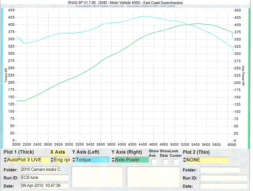 Having enjoyed the car for several months, the top end drop-off started to get old real quick. I was not ready to financially go all-in with a blower just yet so I figured the next logical step was a cam. Going back and forth in my mind whether or not I was going to do a blower in the future I finally decided I did not want to have any "do-overs" and even though I would be staying N/A for possibly another year or so I wanted to do a blower friendly cam now to avoid putting in a big N/A cam that wouldn't play nice with a blower later on. My main goals for choosing a cam were threefold. I did not want to lose too much drivability/low-end torque, I wanted to maintain the nice mid-range torque that I already had, and finally and most importantly I wanted the car to pul hard and make power all the way to the rev limiter. I knew how much RWHP I would probably pick up with a blower cam after having seen what others picked up at peak but I was more concerned with everything under the curve and not falling off at the top. Over the course of a few months I spent some time with Mike Moran at ECS and even some more time on the phone and via email with him and Chris Coriell discussing what my goals for the car were in the near term as well as later on. Based on those goals and the blower in the future Mike and Chris recommended I go with the custom Big Blower Cam grind that they have developed in-house and has been used in the Corvette community for years now with rave reviews. If you ask me what the specs are on the cam I have no idea, if you ask any of them you'll get either "duration in the 220's and lift around 580" or my favorite answer I've seen them give is "it's lumpy". To be honest, I could care less what the actual specs are because what was more important was Mike showing me dyno sheet after dyno sheet of cars similar to mine (CAI and Long Tubes) with the Big Blower Cam and it gave a very consistent picture of what kind of results they achieve with that setup. An example of this was the following sheet they sent over depicting a 2010 Camaro LS3 with the same CAI and LT's I was running and their Big Blower Cam. When I compared it to my earlier sheet it did what I wanted in that it didn't seem to lose much at all down low, still had the healthy mid-range, and pulled all the way to the end. Now I know this wasn't my car and all cars are slightly different but every sheet I had seen painted a similar picture and it was enough for me to know I was going with the right cam and having the right shop tune it. (I would ignore some of the comments in red below as the car obviously didn't make 560 RWHP here) 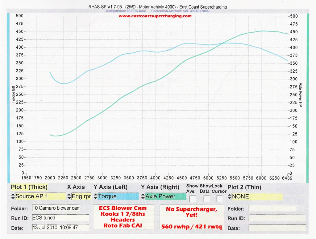 I had fun driving the car un-tuned to ECS fighting to keep it alive at every Stop sign and red traffic light along the way as it didn't even bother to try and find idle and would just konk out, revving the engine at every stop got me some funny looks to say the least. Luckily I am only about 30 miles from ECS and most of them are highway miles so I just took it easy on the car and kept things under 2500 rpms to play it safe. Pulled up up to the shop in the early afternoon and after some prep work setting up the wideband by Matt the shop manager, Doug Ring jumped in the driver's seat with laptop in hand and started working on the car's idle and then took it out on the road to further data log and tune for drivability. Once back from the street it was into the dyno garage where Doug spent a good amount of time working out partial throttle performance before getting into WOT tuning. It didn't take long for Doug to bring the car from its initial WOT pull of 438 RWHP up to a pull of 463 RWHP. Satisfied with what he was seeing in the data logs, Doug finished things off with a pair of back to back pulls that resulted in 460 RWHP followed immediately by the final 455 RWHP pull. His explanation for the back to back pulls was simple, he got the 463 pull a few minutes earlier so if he could jump in again and get solid pulls back to back without issue in the data logs, the final pull represented a very realistic number that the car could consistently put down out on the street. He easily coulda sat around for 5-10 minutes to play dyno-games and get a 465-470 pull out of the car but the 455 on a heat soaked engine, on this dyno, on this day was a much more realistic number. The one thing we forgot to do was do one final pull with the NOWEEDS Exhaust Diverters open as it would have been nice to see another pull done a minute or so after the back to back pulls to see what the gain would have been with the open exhaust. I wound up going back down to ECS a week later when they were able to fit me in for some pulls to get the closed/open diverter comparison. I got to the shop first thing int he morning and after Matt got in a handful of pulls to get some heat into the dyno he did two pulls separated by 15 seconds, first with the diverters closed and then open and the car picked up 9 RWTQ and 10 RWHP on the second pull. The open exhaust really started to show itself above 5000 rpms and if Matt had let the car cool for a few minutes it might have pulled 15-20 more at the wheels but then again that would be playing dyno-games. I discuss the diverters a little more in another thread. The diverter pulls were off a bit from the pulls done the day the car was tuned (only 10 RWHP with the diverters closed) but it was chalked up to different day and maybe not a fully warmed up dyno but the thing that really maters is the back to back closed/open pulls showed there was a gain to be had and possibly even more of a gain later on when the blower goes on. The final sheet I walked away with shows a couple of things, most importantly to me it achieved the goals I wanted to in the first place by barely loosing any power down low, keeping the solid mid-range, and then pulling all the way to the limiter (which was set at 7000 rpms now). Secondly, my sheet backed up the recommendation Chris and Mike had made and confirmed the results of all the other sheets they had shown me of similar setups, and I am not even mention the sheets I had seen of cars with this setup along with a blower and meth on top of them  . .It lost a little bit below 3000, held the mid-range dead on from 3000 to 4500, and beyond 4500 she just starts to sing... 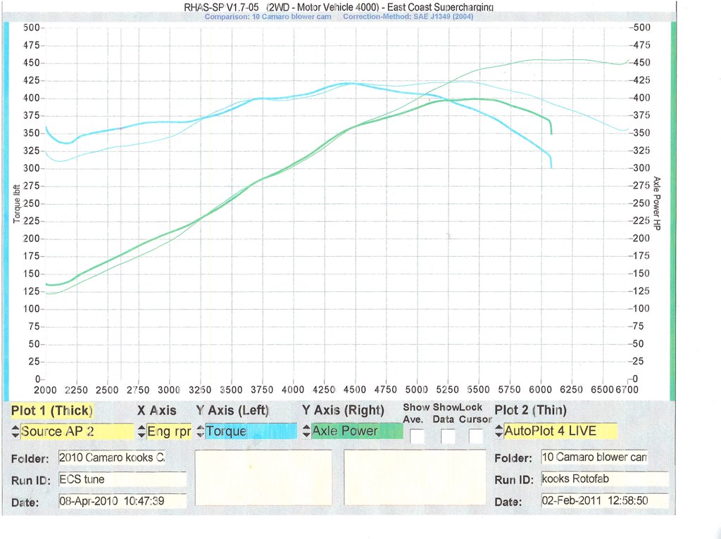 Having driven the car a number of times in the past week I really can't speak for how hard it pulls on the street because it keeps breaking lose in 1st and 2nd since it is so cold out here in Jersey right now. In the battle for traction between 315 Nitto Invos and 17 degree temps, the 17 degree temps win out so a full review will have to wait for warmer temps and when I finally venture out to Raceway Park in Englishtown, NJ (20 minutes from my house  ) for the Wednesday night Test & Tune on the 1320'. I never made it out to the track last year and don't know why, oh yeah, job, wife, bunch of kids, now I remember, but I am going to make it a point to get out there this year so I can at least put some times against that dyno sheet and hopefully not embarrass myself in the process (I have NEVER been down the 1320... EVER... ) for the Wednesday night Test & Tune on the 1320'. I never made it out to the track last year and don't know why, oh yeah, job, wife, bunch of kids, now I remember, but I am going to make it a point to get out there this year so I can at least put some times against that dyno sheet and hopefully not embarrass myself in the process (I have NEVER been down the 1320... EVER...  ), get ready for some three second 60's . ), get ready for some three second 60's .Drivability of the car has been great so far. I have never had a car that has been "cammed" before, as a matter of fact I have never had a performance car before so I have nothing to compare it to. Cruising on the highway in 6th gear anywhere between 1000 and 1500 rpms and there isn't even a hint of surging then again I am usually at 2000 rpms in the 6th just to keep up with everybody here on the Interstates and Turnpike in Jersey so not much of a chance for surging anyway. In parking lots and creeping through my neighborhood I have had to adjust how I drive the car a bit. Chris at ECS warned me that creeping around between 1200-1300 rpm I could see some bucking and he was dead on. I usually creep through the neighborhood in 3rd around 1200 rpm to stay below 25mph and keep the exhaust note down, I can still do that but if I get off the throttle too much it starts to buck, dropping down to second and running at 1700 or so eliminates all the bucking altogether. In parking lots it is the same story, I used to creep around in 2nd at 1100-1200 and if I get off the throttle too much it'll buck a bit, drop to 1st and 1700 or so and everything is fine I just have to get into the clutch a little sooner when slowing down for speed bumps or pedestrians (here in Jersey the two sometimes get confused and when they do there are hit-n-run headlines in the papers )Overall I am totally happy with the results. From Chris and Mike working with me on the details of what I wanted to do with the car now with the future in mind and tolerating my indecision and at times pestering, to Doug tuning the car as thoroughly and consistently as he does after having come back to the garage to accommodate me after having left for the day, and Matt fitting me in to get the diverter comparison pulls in despite the workload queued up for the dyno, I can't say enough good things about how I have been treated at ECS. From the time I walked in last year to get the CAI/Headers tune they have treated me as if I had been going there for years and I would not hesitate to recommend them to anyone Now I just gotta start refilling that coin jar for the Centri Blower and Meth kit to go on next winter. I've seen the sheets and what the ECS guys can do with them on top of an LS3 and their Big Blower Cam Update added 02/16/2011; In regard to fuel economy, I just got back from a 450 mile round trip venture down to Virginia and on the Interstate averaged 24mpg on the way down (until of course I got to the traffic on the DC 495 loop ) and then a solid 24mpg all the way home with the cruise control set at 1950rpm in 6th with the manual 3.45's, you do the math, I shall not incriminate myself
__________________
"When the people find they can vote themselves money, that will herald the end of the republic." - Benjamin Franklin LS3 Camshaft Swap Do-It-Yourself Instructions - 2010 LS3 gone but not forgotten!!! Last edited by robertway; 07-20-2012 at 04:24 PM. |
|
|
|
|
01-20-2011, 03:30 PM
|
#3 |
   
Drives: 2011 ss camaro Join Date: Aug 2010
Location: spring hill, fl
Posts: 1,705
|
great post and pics.

__________________
10/28/2010 got it
|
|
|
|
|
01-20-2011, 03:34 PM
|
#4 |
|
Camaro➎ moderator

|
Wow, this has got to be one of the most impressive DYI's I've seen on here.
__________________
 |
|
|
|
|
01-20-2011, 03:56 PM
|
#5 |
Drives: 2010 Black 1SS Join Date: Aug 2009
Location: Langley BC
Posts: 666
|
Excellent Excellent Excellent!
Just making me want to do my cam even sooner!
__________________
2010 Black 1SS LS3 M6
Power: Kook's 1 7/8" Long Tubes and 3" Exhaust, Injen Full Length CAI, Jannetty Tune Drivetrain: MGW Short Shifter, Street Slayer Twin Clutch, DSS 1 Piece Aluminum Driveshaft, DSS 1000HP Axles, BMR Pro and Delrin Diff Bushings Suspension: BMR Trailing Arms and Bushings, FE6 Swaybar Conversion With Pedders 27mm Front and 32mm Rear ZL1 Swaybars and Links Chassis: Hotchkis Chassis Max Brace, BMR Pro Cradle Bushings Exterior:: Shine by Adam's. ...and plenty more |
|
|
|
|
01-20-2011, 04:02 PM
|
#6 |
|
Drives: 2010 Black 1SS Join Date: Aug 2009
Location: Langley BC
Posts: 666
|
Also, anyone else who has done this who has some "tricks" should add them here too to make the post even more useful.
__________________
2010 Black 1SS LS3 M6
Power: Kook's 1 7/8" Long Tubes and 3" Exhaust, Injen Full Length CAI, Jannetty Tune Drivetrain: MGW Short Shifter, Street Slayer Twin Clutch, DSS 1 Piece Aluminum Driveshaft, DSS 1000HP Axles, BMR Pro and Delrin Diff Bushings Suspension: BMR Trailing Arms and Bushings, FE6 Swaybar Conversion With Pedders 27mm Front and 32mm Rear ZL1 Swaybars and Links Chassis: Hotchkis Chassis Max Brace, BMR Pro Cradle Bushings Exterior:: Shine by Adam's. ...and plenty more |
|
|
|
|
01-20-2011, 04:22 PM
|
#7 |
 Drives: 2010 Camaro SS Join Date: Feb 2010
Location: Oklahoma
Posts: 247
|
The Crane Cams LS3 Valve spring tool is outstanding. Two valves at a time. Very compact and robust.
|
|
|
|
|
01-20-2011, 05:23 PM
|
#8 | |
|
Drives: 2012 Challenger SRT8 Auto Join Date: Sep 2009
Location: Central New Jersey
Posts: 839
|
Quote:
__________________
"When the people find they can vote themselves money, that will herald the end of the republic." - Benjamin Franklin LS3 Camshaft Swap Do-It-Yourself Instructions - 2010 LS3 gone but not forgotten!!! |
|
|
|
|
|
01-20-2011, 06:40 PM
|
#9 |
 Drives: 2010 camaro ss automatic Join Date: May 2010
Location: bronx, N.Y.
Posts: 182
|
By FAR the best, clearest and most in depth DYI instructions i've ever seen. Even the pics and videos were HD quality. Thanks, but I don't have the balls to do this myself though.
|
|
|
|
|
01-20-2011, 06:46 PM
|
#10 |

|
Awesome write up. I was watching the video and was wondering if you have a leak on your oil cooler? Saw some oil on the bottom of something by the filter and I couldn't tell if it was the cooler.
|
|
|
|
|
01-20-2011, 06:50 PM
|
#11 |

Drives: 2010 Camaro Join Date: Aug 2009
Location: Quahog, Rhode Island
Posts: 1,171
|
Great write up!

__________________
 |
|
|
|
|
01-20-2011, 07:15 PM
|
#12 | |
|
Drives: 2012 Challenger SRT8 Auto Join Date: Sep 2009
Location: Central New Jersey
Posts: 839
|
Quote:
Thanks for pointing it out. And thanks to everyone for the compliments so far....
__________________
"When the people find they can vote themselves money, that will herald the end of the republic." - Benjamin Franklin LS3 Camshaft Swap Do-It-Yourself Instructions - 2010 LS3 gone but not forgotten!!! |
|
|
|
|
|
01-20-2011, 07:24 PM
|
#13 |

Drives: 2010 Camaro SS Join Date: Jan 2011
Location: Petawawa, ON
Posts: 151
|
Amazing write-up...makes me want to start my cam install this winter rather than wait for the summer...thanks for all your hard work.
|
|
|
|
|
01-20-2011, 07:28 PM
|
#14 |

Drives: IOM 2SS/RS M6 Join Date: Oct 2009
Location: Kenosha, Wisconsin
Posts: 240
|
Fantastic job on the write up. I will be using this beginning next week for my cam swap...
__________________
2010 2SS..LS3..Procharger..4l80e..DSS 9"
|
|
|
|
|
|
|
|
 |
| Thread Tools | |
|
|
 Similar Threads
|
||||
| Thread | Thread Starter | Forum | Replies | Last Post |
| DIY: Vararam CAI Install with Color Photos | Jeanius | Camaro DIY & HOW-TO instructions & discussions | 22 | 05-26-2015 02:48 PM |
| DIY Hurst Short Throw Shifter Install - Pix and Video | TAG UR IT | Camaro DIY & HOW-TO instructions & discussions | 121 | 02-26-2015 10:08 AM |
| Camaro Heritage Grill DIY install (now with official GM install instructions). | vuduman67 | Camaro DIY & HOW-TO instructions & discussions | 216 | 12-03-2014 05:18 PM |
| DIY : Install underdrive pulley on 2010 Camaro SS | Nine Ball | Camaro DIY & HOW-TO instructions & discussions | 34 | 09-30-2013 08:25 PM |


